Д ля
ля
обозначения плоскостей и направлений
кристалла используются так называемые
кристаллографические индексы Миллера.
Для их получения проведем оси координатX,Y,Z
вдоль базисных векторов
![]() .
.
Пусть некоторая плоскость пересекает
такую координатную систему в точках с
координатами:
![]() ;
;
![]() ;
;![]() .
.
![]() — целые или дробные числа, выражают
— целые или дробные числа, выражают
наклон плоскостей по отношению к осям
координатной системы. Теперь составим
отношение обратных чисел![]() и приведем это отношение к отношению
и приведем это отношение к отношению
наименьших целых чисел:
![]() ;
;
R —
наименьшее
кратное, а h,
k, l и есть
индексы Миллера для указанной плоскости.
При обозначении плоскостей индексы
Миллера заключаются в круглые скобки,
без каких либо знаков между ними.
Предположим
![]() ;
;
![]() ;
;
![]() .
.
Такие же индексы будут иметь остальные
плоскости параллельные ей. Если плоскость
параллельна одной из координатных осей,
то соответствующий индекс равен нулю,
если плоскость отсекает координату при
отрицательных значениях, то над
соответствующим индексом Миллера сверху
ставится знак“-”.
Направления перпендикулярные плоскости
(hkl)
обозначаются теми же индексами
заключенными в квадратные скобки
[hkl]. Система
плоскостей одного кристаллографического
типа обозначаются {hkl},
направления обозначаются <hkl>.
Для примера найдем обозначения характерных
плоскостей и направлений в кристаллах
кубической системы
(а1
= а2
= а3
= а;
α = β= γ= 900).
Для этого
вырежем кристалл в форме куба с ребрами
вдоль базисных векторов
![]() .
.
Осиx,
,y, z н аправлены
вдоль базисных векторов. Найдем индексы
Миллера для заштрихованной плоскости
1. Она пересекает координатные оси в
точках с координатами:
![]() ;
;
![]() ;
;
![]() .
.
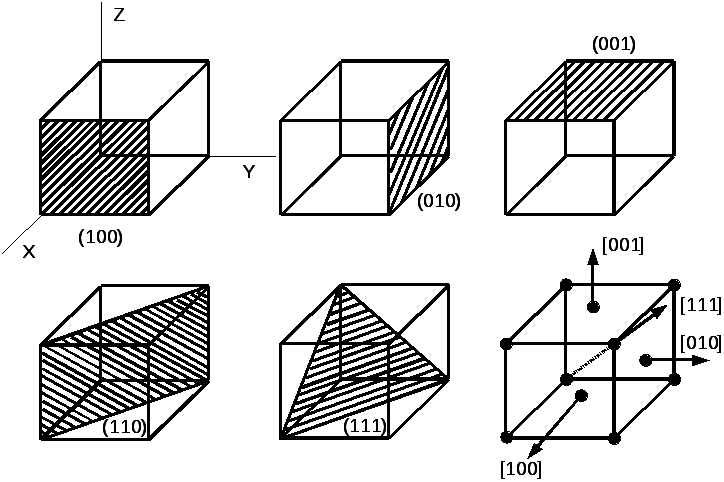
Тогда индексы Миллера для плоскости 2:
(010), для 3:
(001). x1[100],
y1[010],
z1[001].
Плоскость противоположную (100), обозначают
![]() и так д
и так д алее.
алее.
В се
се
плоскости (100), (010), (001),![]() ,
,![]() ,
,![]() кристаллографически одинаковые и их
кристаллографически одинаковые и их
обозначают {100}.
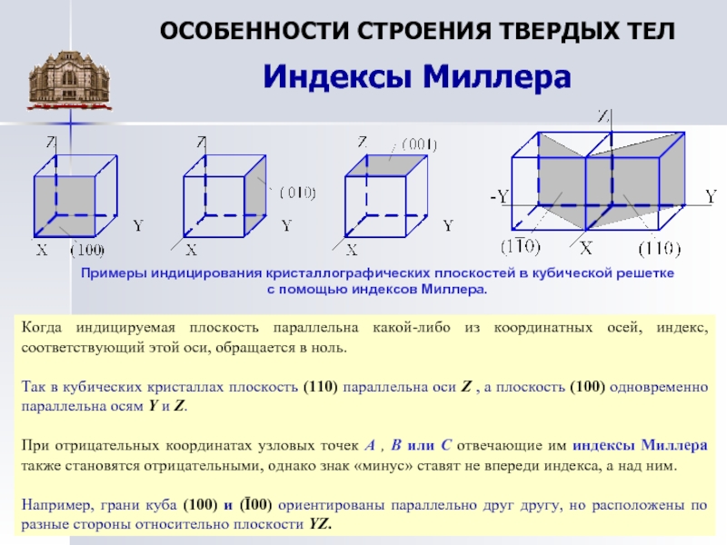
На рисунке заштрихована плоскость
(110), для этой плоскости одинаковыми
являются плоскости (011), (101). На следующем
рисунке заштрихована плоскость (111). Для
обозначения плоскостей в кристаллах
гексагональной системы используют 4
индекса Миллера, для этого проводят
чет ыре
ыре
координатные осиx,
y, u, z,. Ось z
параллельна ребру а3.
![]() ;
;
![]() .
.
Плоскость
перпендикулярная оси
![]() называется базисной плоскостью. Осиx,
называется базисной плоскостью. Осиx,
y, u располагают
в базисной плоскости под углом 1200
друг к другу. Для тог чтобы найти (hkil),
находят координаты точек пересечения
с кристаллографическими осями.
Д ля
ля
примера найдем индексы Миллера для
плоскости АВ, которая перпендикулярна
плоскости рисунка. Координаты точек
пересечения этой плоскостью координатных
осей:
![]() ,
,![]() ;
;
![]() ;
;
![]() .
.
Следовательно, направления вдоль осиz
есть [0001],
i = — (h+k).
Возникает вопрос, почему используем
четыре а не три индекса Миллера при
обозначении плоскостей и направлений
в кристаллах гексагональной системы.
Оказывается, что при обозначении тремя
индексами Миллера однотипные плоскости
кристаллов гексагональной системы
имели бы разное число единиц и нулей, и
их нельзя было бы обозначить как {hkl}.
Для примера уберем ось u,
тогда плоскости СВ=(010),
![]() ,
,![]() .
.
Обозначение этих плоскостей имеют вид:
![]() ,
,![]() ,
,
видно что все однотипные плоскостиCB,
DB, DF, FL имеют
две единицы и два нуля, и тогда их можно
обозначить {1100}.
From Wikipedia, the free encyclopedia

Planes with different Miller indices in cubic crystals

Miller indices form a notation system in crystallography for lattice planes in crystal (Bravais) lattices.
In particular, a family of lattice planes of a given (direct) Bravais lattice is determined by three integers h, k, and ℓ, the Miller indices. They are written (hkℓ), and denote the family of (parallel) lattice planes (of the given Bravais lattice) orthogonal to  , where
  are the basis or primitive translation vectors of the reciprocal lattice for the given Bravais lattice. (Note that the plane is not always orthogonal to the linear combination of direct or original lattice vectors
  because the direct lattice vectors need not be mutually orthogonal.) This is based on the fact that a reciprocal lattice vector
  (the vector indicating a reciprocal lattice point from the reciprocal lattice origin) is the wavevector of a plane wave in the Fourier series of a spatial function (e.g., electronic density function) which periodicity follows the original Bravais lattice, so wavefronts of the plane wave are coincident with parallel lattice planes of the original lattice. Since a measured scattering vector in X-ray crystallography,
  with
with  as the outgoing (scattered from a crystal lattice) X-ray wavevector and
  as the incoming (toward the crystal lattice) X-ray wavevector, is equal to a reciprocal lattice vector as stated by the Laue equations, the measured scattered X-ray peak at each measured scattering vector
  is marked by Miller indices. By convention, negative integers are written with a bar, as in 3 for −3. The integers are usually written in lowest terms, i.e. their greatest common divisor should be 1. Miller indices are also used to designate reflections in X-ray crystallography. In this case the integers are not necessarily in lowest terms, and can be thought of as corresponding to planes spaced such that the reflections from adjacent planes would have a phase difference of exactly one wavelength (2π), regardless of whether there are atoms on all these planes or not.
There are also several related notations:[1]
- the notation {hkℓ} denotes the set of all planes that are equivalent to (hkℓ) by the symmetry of the lattice.
In the context of crystal directions (not planes), the corresponding notations are:
- [hkℓ], with square instead of round brackets, denotes a direction in the basis of the direct lattice vectors instead of the reciprocal lattice; and
- similarly, the notation <hkℓ> denotes the set of all directions that are equivalent to [hkℓ] by symmetry.
Note, for Laue-Bragg interferences
- hkl lacks any bracketing when designating a reflection
Miller indices were introduced in 1839 by the British mineralogist William Hallowes Miller, although an almost identical system (Weiss parameters) had already been used by German mineralogist Christian Samuel Weiss since 1817.[2] The method was also historically known as the Millerian system, and the indices as Millerian,[3] although this is now rare.
The Miller indices are defined with respect to any choice of unit cell and not only with respect to primitive basis vectors, as is sometimes stated.
Definition[edit]

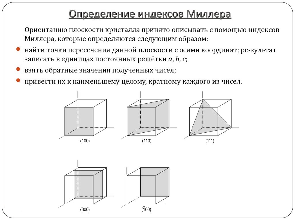
Examples of determining indices for a plane using intercepts with axes; left (111), right (221)
There are two equivalent ways to define the meaning of the Miller indices:[1] via a point in the reciprocal lattice, or as the inverse intercepts along the lattice vectors. Both definitions are given below. In either case, one needs to choose the three lattice vectors a1, a2, and a3 that define the unit cell (note that the conventional unit cell may be larger than the primitive cell of the Bravais lattice, as the examples below illustrate). Given these, the three primitive reciprocal lattice vectors are also determined (denoted b1, b2, and b3).
Then, given the three Miller indices h, k, ℓ, (hkℓ) denotes planes orthogonal to the reciprocal lattice vector:

That is, (hkℓ) simply indicates a normal to the planes in the basis of the primitive reciprocal lattice vectors. Because the coordinates are integers, this normal is itself always a reciprocal lattice vector. The requirement of lowest terms means that it is the shortest reciprocal lattice vector in the given direction.
Equivalently, (hkℓ) denotes a plane that intercepts the three points a1/h, a2/k, and a3/ℓ, or some multiple thereof. That is, the Miller indices are proportional to the inverses of the intercepts of the plane, in the basis of the lattice vectors. If one of the indices is zero, it means that the planes do not intersect that axis (the intercept is «at infinity»).
Considering only (hkℓ) planes intersecting one or more lattice points (the lattice planes), the perpendicular distance d between adjacent lattice planes is related to the (shortest) reciprocal lattice vector orthogonal to the planes by the formula:  .[1]
.[1]
The related notation [hkℓ] denotes the direction:

That is, it uses the direct lattice basis instead of the reciprocal lattice. Note that [hkℓ] is not generally normal to the (hkℓ) planes, except in a cubic lattice as described below.
Case of cubic structures[edit]
For the special case of simple cubic crystals, the lattice vectors are orthogonal and of equal length (usually denoted a), as are those of the reciprocal lattice. Thus, in this common case, the Miller indices (hkℓ) and [hkℓ] both simply denote normals/directions in Cartesian coordinates.
For cubic crystals with lattice constant a, the spacing d between adjacent (hkℓ) lattice planes is (from above)
 .
.

Because of the symmetry of cubic crystals, it is possible to change the place and sign of the integers and have equivalent directions and planes:
- Indices in angle brackets such as ⟨100⟩ denote a family of directions which are equivalent due to symmetry operations, such as [100], [010], [001] or the negative of any of those directions.
- Indices in curly brackets or braces such as {100} denote a family of plane normals which are equivalent due to symmetry operations, much the way angle brackets denote a family of directions.
For face-centered cubic and body-centered cubic lattices, the primitive lattice vectors are not orthogonal. However, in these cases the Miller indices are conventionally defined relative to the lattice vectors of the cubic supercell and hence are again simply the Cartesian directions.
Case of hexagonal and rhombohedral structures[edit]
With hexagonal and rhombohedral lattice systems, it is possible to use the Bravais-Miller system, which uses four indices (h k i ℓ) that obey the constraint
- h + k + i = 0.
Here h, k and ℓ are identical to the corresponding Miller indices, and i is a redundant index.
This four-index scheme for labeling planes in a hexagonal lattice makes permutation symmetries apparent. For example, the similarity between (110) ≡ (1120) and (120) ≡ (1210) is more obvious when the redundant index is shown.
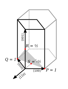
In the figure at right, the (001) plane has a 3-fold symmetry: it remains unchanged by a rotation of 1/3 (2π/3 rad, 120°). The [100], [010] and the [110] directions are really similar. If S is the intercept of the plane with the [110] axis, then
- i = 1/S.
There are also ad hoc schemes (e.g. in the transmission electron microscopy literature) for indexing hexagonal lattice vectors (rather than reciprocal lattice vectors or planes) with four indices. However they don’t operate by similarly adding a redundant index to the regular three-index set.
For example, the reciprocal lattice vector (hkℓ) as suggested above can be written in terms of reciprocal lattice vectors as  . For hexagonal crystals this may be expressed in terms of direct-lattice basis-vectors a1, a2 and a3 as

Hence zone indices of the direction perpendicular to plane (hkℓ) are, in suitably normalized triplet form, simply ![[2h+k,h+2k,ell (3/2)(a/c)^{2}]](https://wikimedia.org/api/rest_v1/media/math/render/svg/e61cc8b8ca771b1f5320ad434a259f4a7b5ca2f5) . When four indices are used for the zone normal to plane (hkℓ), however, the literature often uses
. When four indices are used for the zone normal to plane (hkℓ), however, the literature often uses ![[h,k,-h-k,ell (3/2)(a/c)^{2}]](https://wikimedia.org/api/rest_v1/media/math/render/svg/38305e550589df7460613db452a453148c846210) instead.[4] Thus as you can see, four-index zone indices in square or angle brackets sometimes mix a single direct-lattice index on the right with reciprocal-lattice indices (normally in round or curly brackets) on the left.
instead.[4] Thus as you can see, four-index zone indices in square or angle brackets sometimes mix a single direct-lattice index on the right with reciprocal-lattice indices (normally in round or curly brackets) on the left.
And, note that for hexagonal interplanar distances, they take the form

Crystallographic planes and directions[edit]

Dense crystallographic planes
Crystallographic directions are lines linking nodes (atoms, ions or molecules) of a crystal. Similarly, crystallographic planes are planes linking nodes. Some directions and planes have a higher density of nodes; these dense planes have an influence on the behavior of the crystal:
- optical properties: in condensed matter, light «jumps» from one atom to the other with the Rayleigh scattering; the velocity of light thus varies according to the directions, whether the atoms are close or far; this gives the birefringence
- adsorption and reactivity: adsorption and chemical reactions can occur at atoms or molecules on crystal surfaces, these phenomena are thus sensitive to the density of nodes;
- surface tension: the condensation of a material means that the atoms, ions or molecules are more stable if they are surrounded by other similar species; the surface tension of an interface thus varies according to the density on the surface
- Pores and crystallites tend to have straight grain boundaries following dense planes
- cleavage
- dislocations (plastic deformation)
- the dislocation core tends to spread on dense planes (the elastic perturbation is «diluted»); this reduces the friction (Peierls–Nabarro force), the sliding occurs more frequently on dense planes;
- the perturbation carried by the dislocation (Burgers vector) is along a dense direction: the shift of one node in a dense direction is a lesser distortion;
- the dislocation line tends to follow a dense direction, the dislocation line is often a straight line, a dislocation loop is often a polygon.
For all these reasons, it is important to determine the planes and thus to have a notation system.
Integer vs. irrational Miller indices: Lattice planes and quasicrystals[edit]
Ordinarily, Miller indices are always integers by definition, and this constraint is physically significant. To understand this, suppose that we allow a plane (abc) where the Miller «indices» a, b and c (defined as above) are not necessarily integers.
If a, b and c have rational ratios, then the same family of planes can be written in terms of integer indices (hkℓ) by scaling a, b and c appropriately: divide by the largest of the three numbers, and then multiply by the least common denominator. Thus, integer Miller indices implicitly include indices with all rational ratios. The reason why planes where the components (in the reciprocal-lattice basis) have rational ratios are of special interest is that these are the lattice planes: they are the only planes whose intersections with the crystal are 2d-periodic.
For a plane (abc) where a, b and c have irrational ratios, on the other hand, the intersection of the plane with the crystal is not periodic. It forms an aperiodic pattern known as a quasicrystal. This construction corresponds precisely to the standard «cut-and-project» method of defining a quasicrystal, using a plane with irrational-ratio Miller indices. (Although many quasicrystals, such as the Penrose tiling, are formed by «cuts» of periodic lattices in more than three dimensions, involving the intersection of more than one such hyperplane.)
See also[edit]
- Crystal structure
- Crystal habit
- Kikuchi line
- Zone axis
References[edit]
- ^ a b c Ashcroft, Neil W.; Mermin, N. David (1976). Solid state physics. New York: Holt, Rinehart and Winston. ISBN 0030839939. OCLC 934604.
- ^ Weiss, Christian Samuel (1817). «Ueber eine verbesserte Methode für die Bezeichnung der verschiedenen Flächen eines Krystallisationssystems, nebst Bemerkungen über den Zustand der Polarisierung der Seiten in den Linien der krystallinischen Structur». Abhandlungen der physikalischen Klasse der Königlich-Preussischen Akademie der Wissenschaften: 286–336.
- ^ Oxford English Dictionary Online (Consulted May 2007)
- ^ J. W. Edington (1976) Practical electron microscopy in materials science (N. V. Philips’ Gloeilampenfabrieken, Eindhoven) ISBN 1-878907-35-2, Appendix 2
External links[edit]
- IUCr Online Dictionary of Crystallography
- Miller index description with diagrams
- Online tutorial about lattice planes and Miller indices.
- MTEX – Free MATLAB toolbox for Texture Analysis
- http://sourceforge.net/projects/orilib – A collection of routines for rotation / orientation manipulation, including special tools for crystal orientations.
Любой кристалл можно описать, используя аналитическую геометрию, выбирая оси и называя их кристаллографическими. Как правило, они располагаются по ребрам элементарной ячейки. Существует несколько методик, одна из которых считается универсальной. Речь о миллеровских индексах плоскости, представляющих собой числа, образованные отсекаемым на кристаллографических осях плоскостями.
Индексирование по Миллеру
Кристаллографические индексы Миллера — это характеристики расположения в кристаллах атомных плоскостей. Они связаны с отрезками на трех осях системы координат (любые три линии, не лежащие в одной плоскости и параллельные ребрам кристалла), образованными выбранной параметрической (масштабной) плоскостью, параллельной грани кристалла, и пересекающей оси координат. Выбор кристаллографической плоскости произвольный. Существует три модели относительного размещения ось/плоскость:
- с пересечением плоскости со всеми осями;
- с пересечением двух осей и относительно третьей — параллельно;
- с пересечением одной оси и ориентированных параллельно по отношению к двум другим.
В итоге индексы Миллера – это тройка простых целых чисел, помещенных в круглые скобки. Например: (110), (100), (111).
Индексирование — процедура, позволяющая описать плоскости в кристалле. С этой целью по оси Х определяется направление оси решетки А, по оси Y — B, Z — С. Эта система координат применима к типу решетки, т.е. это не орторомбическая система координат, поэтому соответствующие ей правила в ней применяются не сразу.
Чтобы в кристаллической решетке описать направления, через начало координат проводят прямую, и определяют вектором точку Р по формуле: r=uа+vb+wc, где:
х=u;
у=v;
z=w.
Значения u, v, w — индексы искомых кристаллографических направлений для обозначения которых используются квадратные скобки, например, [uvw]-направление. Это определение применяется только при кратности индексов произвольной константе (fu, fv, fw), поскольку в указании направления главную роль выполняют отношения u:v:w.
Как правило, константа должна подбираться таким образом, что v, w оказываются целыми числами, то есть записывается не [1/4, 1/3, 1/12], а [341] (f=12) или [422] [211] (f=1/2). С черточкой вверху записываются отрицательные значения кристаллографических индексов.
Трехмерная решетка кристалла представляется как группа атомных плоскостей, образованных содержащимися в них атомами, параллельных и равноудаленных друг от друга. Индексы Миллера покажут отношение длины отрезков, осекаемых заданной и параметрической плоскостями. Несколько слов о том, какие плоскости в кристалле называются главными: по сути это любая плоскость, пересекающая оси координат.
Индексы Миллера в металлургии
Индексы Миллера активно используются для анализа свойств сплавов, Например, такие металлы, как никель, платина специфически взаимодействуют плоскостями кристаллов с серой. В результате повышаются такие показатели, как активность и селективность. Этот эффект возникает как следствие перестройки поверхности катализатора, а также из-за разницы параметров поверхностной энергии плоскостей металлов, имеющих небольшие значения индексов Миллера.
Поскольку определение единичной плоскости осуществляется произвольно, можно определить несколько пакетов индексов Миллера, по которым можно судить о каталитической активности плоскостей при воздействии на металлы с помощью структурно-чувствительных реакций гидрогенолиза, гидрогенизации и изомеризации.