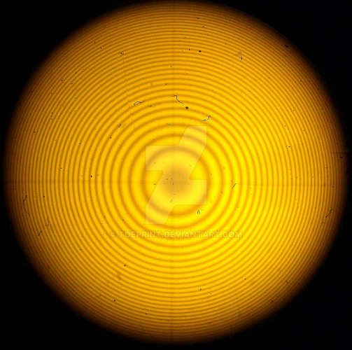
Частный
случай полос равной толщины — кольца
Ньютона —
наблюдаются, если плосковыпуклую линзу
поместить на плоскопараллельную
стеклянную пластинку (рис 3).
Если
на линзу падает пучок монохроматического
света, то световые волны, отражённые от
воздуха в точке А
и от стекла в точке В
(т.е. от
верхней и нижней границ воздушной
прослойки), оказываются когерентными
и интерферируют. Волна, отраженная от
плоской поверхности линзы, не когерентна
с ними и дает лишь равномерную засветку.
Точки, для которых толщина воздушного
зазора одинакова, располагаются на
окружностях, поэтому интерференционная
картина имеет вид чередующихся
концентрических темных и светлых колец.

Рис.3. Схема
возникновения колец Ньютона
Так как отражение
световой волны в точке В происходит от
стекла (оптически более плотной среды),
то оптическая длина пути второго луча
в точке А составит АВ + ВА + λ/2. Оптическая
длина пути первого луча в точке А равна
нулю. Поэтому
Δопт
= L2—
L1
= АВ + ВА + λ/2 = 2d
+ λ / 2
Тёмные кольца
образуются там, где оптическая разность
хода равна нечётному числу полуволн:
Δопт
= 2d
+ λ
/2 = (2m
+ 1) λ
/2,
т.е. при толщине
зазора
d
= m
λ
/2 , (8)
где
m
= 0,1,2,3… — номер кольца.
В
центре интерференционной картины
находится темный круг, соответствующий
минимуму нулевого порядка. Если rm
— радиус темного кольца под номером m,
то из треугольника AОС (см. рис.3) имеем:
rm2
=
R2
— (R
— d,)2
= 2Rd
– d
2,
(9)
где
R
— радиус кривизны линзы. Полагая величину
воздушного зазора в месте возникновения
колец малой, (т.е. пренебрегая d
2
по сравнению с 2Rd),
получим:
rm
2 = 2Rd.
.
Подставляя
сюда (8), получим
rm2
= Rmλ
(10)
Из этой формулы
видно, что зная длину волны используемого
света радиус кривизны линзы можно найти
путем измерения радиуса кольца Ньютона
и определения его порядкового номера.
Использование
формулы (10) для определения радиуса
кривизны может привести к ошибке, т.к.
в точке соприкосновения линзы и стеклянной
пластинки возможна деформация, как
линзы, так и пластинки, сравнимая по
величине с длиной волны света. Поэтому
результаты, полученные без учета этого
факта, являются неточными.
Величина
воздушного зазора оказывается меньше
теоретической величины, полученной из
рис.3, на величину суммарной деформации
стеклянной пластинки и линзы δ (рис.4).
Учитывая это, в формулу (9) вместо толщины
воздушного зазора d
необходимо подставить сумму толщины
воздушного зазора и величины суммарной
деформации линзы и стеклянной пластинки
(d
+ δ):
rm2
=
R2
– [R
–(d+
δ)]2.
Пренебрегая
малой величиной (d+
δ)2,
получаем:
rm2
= 2R(d
+ δ
)

Рис.4.
Учет деформации линзы и стеклянной
пластинки
Учитывая
(13), получим следующую формулу, для
радиусов темных колец Ньютона с учетом
суммарной деформации:
rm2
= Rmλ
+ 2Rδ
(11)
Экспериментально
удобнее вместо радиуса кольца Ньютона
измерять его диаметр (Dm
). В этом
случае формула (11) будет иметь вид:
Dm2
= 4Rmλ
+ 8Rδ,
(12)
Из
(12) видно, что квадрат диаметра кольца
Ньютона Dm2
пропорционален порядковому номеру
кольца m.
Если построить график зависимости Dm2
от m,
то экспериментальные точки должны
лежать на одной прямой, и тангенс угла
наклона этой прямой tgα
будет равен 4Rλ.
Таким образом, для нахождения радиуса
кривизны линзы необходимо, используя
график зависимости Dm2
= f(m),
найти
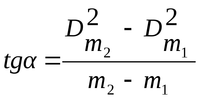 ,
,
(13)
где
m1,
m2
номера колец,
D2m1
и D2m2
– их диаметры,
Радиус кривизны
линзы затем можно рассчитать по формуле
R=tgα/4λ.
(14)
В
центре линзы наблюдается круглое темное
пятно, соответствующее нулевой толщине
воздушного зазора в области деформации.
Измерив диаметр центрального темного
пятна (т.е. темного кольца, номер которого
m=0),
из (12) можно найти величину суммарной
деформации линзы и стеклянной пластинки
по формуле:
δ
= D02/
( 8R
) (15)
Соседние файлы в папке ОПТИКА Лаб.раб 2013
- #
- #
- #
- #
- #
- #
- #
- #
- #
Кольца Ньютона
Кольца Ньютона — это кольцевые полосы равной толщины, наблюдаемые при отражении света от поверхностей зазора между стеклянной пластинкой и соприкасающейся с ней выпуклой линзой.
Они наблюдаются при отражении света от соприкасающихся друг с другом плоскопараллельный толстой стеклянной пластинки и плоско-выпуклой линзы с большим радиусом кривизны. Роль тонкой пленки, от поверхностей которой отражаются когерентные волны, играет воздушный зазор между пластинкой и линзой (вследствие большой толщины пластинки и линзы за счет отражений от других поверхностей интерференционные полосы не возникают). При нормальном падении света полосы равной толщины имеют вид концентрических окружностей, при наклонном падении — эллипсов.
Радиус светлых колец Ньютона в отраженном свете (рис. 1.1, а)
где — номер кольца;
— радиус кривизны линзы;
— длина волны света в вакууме.

рис. 1.1
Радиус темных колец Ньютона в отраженном свете (рис. 1.1, а)
Радиус светлых колец Ньютона в проходящем свете (рис. 1.1, б)
Радиус темных колец Ньютона в проходящем свете (рис. 1.1, б)
Связь толщины воздушной прослойки с радиусом линзы и радиусом -го кольца Ньютона
Интерференция света от двух когерентных источников света (щели Юнга — рис. 1.2, зеркала и бипризмы Френеля):
-
а) положения последовательных интерференционных максимумов:
-
б) положения последовательных интерференционных минимумов:
-
в) расстояние между соседними максимумами или минимумами:
где — координаты максимумов и минимумов интенсивности ;
— расстояние между источниками света;
— расстояние от источников света до экрана (рис. 1.3).

рис. 1.2

рис. 1.3
From Wikipedia, the free encyclopedia

Fig. 1: Newton’s rings observed through a microscope. The smallest increments on the superimposed scale are 100μm. The illumination is from below, leading to a bright central region.
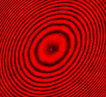
Fig. 2: Newton’s rings interference pattern created by a plano-convex lens illuminated by 650 nm red laser light, photographed using a low-light microscope. The illumination is from above, leading to a dark central region.
![]()
Fig. 3: Arrangement to view Newton’s Rings: a convex lens is placed on top of a flat surface.
Newton’s rings is a phenomenon in which an interference pattern is created by the reflection of light between two surfaces, typically a spherical surface and an adjacent touching flat surface. It is named after Isaac Newton, who investigated the effect in 1666. When viewed with monochromatic light, Newton’s rings appear as a series of concentric, alternating bright and dark rings centered at the point of contact between the two surfaces. When viewed with white light, it forms a concentric ring pattern of rainbow colors because the different wavelengths of light interfere at different thicknesses of the air layer between the surfaces.
History[edit]
The phenomenon was first described by Robert Hooke in his 1665 book Micrographia. Its name derives from the mathematician and physicist Sir Isaac Newton, who studied the phenomenon in 1666 while sequestered at home in Lincolnshire in the time of the Great Plague that had shut down Trinity College, Cambridge. He recorded his observations in an essay entitled «Of Colours». The phenomenon became a source of dispute between Newton, who favored a corpuscular nature of light, and Hooke, who favored a wave-like nature of light.[1] Newton did not publish his analysis until after Hooke’s death, as part of his treatise «Opticks» published in 1704.
Theory[edit]

Fig. 4: Closeup of a section of the top glass on the optical flat, showing how interference fringes form. At positions where the path length difference is equal to an odd multiple(2n+1) of a half-wavelength (a), the reflected waves reinforce, resulting in a bright spot. At positions where the path length difference is equal to an even multiple (2n)of a half-wavelength (b), (Lambda by 2)the reflected waves cancel, resulting in a dark spot. This results in a pattern of concentric bright and dark rings, interference fringes.
The pattern is created by placing a very slightly convex curved glass on an optical flat glass. The two pieces of glass make contact only at the center. At other points there is a slight air gap between the two surfaces, increasing with radial distance from the center, as shown in Fig. 3.
Consider monochromatic (single color) light incident from the top that reflects from both the bottom surface of the top lens and the top surface of the optical flat below it.[2] The light passes through the glass lens until it comes to the glass-to-air boundary, where the transmitted light goes from a higher refractive index (n) value to a lower n value. The transmitted light passes through this boundary with no phase change. The reflected light undergoing internal reflection (about 4% of the total) also has no phase change. The light that is transmitted into the air travels a distance, t, before it is reflected at the flat surface below. Reflection at this air-to-glass boundary causes a half-cycle (180°) phase shift because the air has a lower refractive index than the glass. The reflected light at the lower surface returns a distance of (again) t and passes back into the lens. The additional path length is equal to twice the gap between the surfaces. The two reflected rays will interfere according to the total phase change caused by the extra path length 2t and by the half-cycle phase change induced in reflection at the flat surface. When the distance 2t is zero (lens touching optical flat) the waves interfere destructively, hence the central region of the pattern is dark, as shown in Fig. 2.
A similar analysis for illumination of the device from below instead of from above shows that in this case the central portion of the pattern is bright, not dark, as shown in Fig. 1. When the light is not monochromatic, the radial position of the fringe pattern has a «rainbow» appearance, as shown in Fig. 5.
Constructive interference[edit]
(Fig. 4a): In areas where the path length difference between the two rays is equal to an odd multiple of half a wavelength (λ/2) of the light waves, the reflected waves will be in phase, so the «troughs» and «peaks» of the waves coincide. Therefore, the waves will reinforce (add) and the resulting reflected light intensity will be greater. As a result, a bright area will be observed there.
Destructive interference[edit]
(Fig. 4b): At other locations, where the path length difference is equal to an even multiple of a half-wavelength, the reflected waves will be 180° out of phase, so a «trough» of one wave coincides with a «peak» of the other wave. Therefore, the waves will cancel (subtract) and the resulting light intensity will be weaker or zero. As a result, a dark area will be observed there. Because of the 180° phase reversal due to reflection of the bottom ray, the center where the two pieces touch is dark.
This interference results in a pattern of bright and dark lines or bands called «interference fringes» being observed on the surface. These are similar to contour lines on maps, revealing differences in the thickness of the air gap. The gap between the surfaces is constant along a fringe. The path length difference between two adjacent bright or dark fringes is one wavelength λ of the light, so the difference in the gap between the surfaces is one-half wavelength. Since the wavelength of light is so small, this technique can measure very small departures from flatness. For example, the wavelength of red light is about 700 nm, so using red light the difference in height between two fringes is half that, or 350 nm, about 1/100 the diameter of a human hair. Since the gap between the glasses increases radially from the center, the interference fringes form concentric rings. For glass surfaces that are not spherical, the fringes will not be rings but will have other shapes.
Quantitative Relationships[edit]

Fig. 5: Newton’s rings seen in two plano-convex lenses with their flat surfaces in contact. One surface is slightly convex, creating the rings. In white light, the rings are rainbow-colored, because the different wavelengths of each color interfere at different locations.

Rainbow-colored Newton’s rings on an Agfacolor slide (slightly right of center on the houses and upper right on the mountains).
For illumination from above, with a dark center, the radius of the Nth bright ring is given by
![{displaystyle r_{N}=left[lambda Rleft(N-{1 over 2}right)right]^{1/2},}](https://wikimedia.org/api/rest_v1/media/math/render/svg/42e6b239fd5a47ddcdddcb24d6371338e82e2fc8)
where
N is the bright-ring number, R is the radius of curvature of the glass lens the light is passing through, and λ is the wavelength of the light. The above formula is also applicable for dark rings for the ring pattern obtained by transmitted light.
Given the radial distance of a bright ring, r, and a radius of curvature of the lens, R, the air gap between the glass surfaces, t, is given to a good approximation by

where the effect of viewing the pattern at an angle oblique to the incident rays is ignored.
Thin-film interference[edit]
The phenomenon of Newton’s rings is explained on the same basis as thin-film interference, including effects such as «rainbows» seen in thin films of oil on water or in soap bubbles. The difference is that here the «thin film» is a thin layer of air.
References[edit]
- ^ Westfall, Richard S. (1980). Never at Rest, A Biography of Isaac Newton. Cambridge University Press. p. 171. ISBN 0-521-23143-4.
- ^ Young, Hugh D.; Freedman, Roger A. (2012). University Physics, 13th Ed. Addison Wesley. p. 1178. ISBN 978-0-321-69686-1.
Further reading[edit]
- Airy, G.B. (1833). «VI.On the phænomena of Newton’s rings when formed between two transparent substances of different refractive powers». Philosophical Magazine. Series 3. 2 (7): 20–30. doi:10.1080/14786443308647959. ISSN 1941-5966.
- Illueca, C.; Vazquez, C.; Hernandez, C.; Viqueira, V. (1998). «The use of Newton’s rings for characterizing ophthalmic lenses». Ophthalmic and Physiological Optics. 18 (4): 360–371. doi:10.1046/j.1475-1313.1998.00366.x. ISSN 0275-5408. PMID 9829108. S2CID 222086863.
- Dobroiu, Adrian; Alexandrescu, Adrian; Apostol, Dan; Nascov, Victor; Damian, Victor S. (2000). «Improved method for processing Newton’s rings fringe patterns». In Necsoiu, Teodor; Robu, Maria; Dumitras, Dan C (eds.). SIOEL ’99: Sixth Symposium on Optoelectronics. Proceedings. Vol. 4068. pp. 342–347. doi:10.1117/12.378693. ISSN 0277-786X. S2CID 120241545.
- Tolansky, S. (2009). «XIV. New contributions to interferometry. Part II—New interference phenomena with Newton’s rings». The London, Edinburgh, and Dublin Philosophical Magazine and Journal of Science. 35 (241): 120–136. doi:10.1080/14786444408521466. ISSN 1941-5982.
External links[edit]
- Newton’s Ring from Eric Weisstein’s World of Physics
- Explanation of and expression for Newton’s rings
- Newton’s rings Video of a simple experiment with two lenses, and Newton’s rings on mica observed. (On the website FizKapu.) (in Hungarian)