
Электрическое сопротивление – физическая величина, характеризующая способность проводника препятствовать прохождению по нему электрического тока.
Сопротивление часто обозначается через R или r и в Международной системе единиц (СИ) измеряется в Омах.
В зависимости от среды проводника и носителей зарядов, физическая природа сопротивления может отличаться. Так, например, в металле движущиеся под действием поля электроны рассеиваются на неоднородностях ионной решетки, теряют свой импульс, и энергия их движения преобразуется во внутреннюю энергию кристаллической решетки (то есть становится меньше).
Сопротивление проводника при прочих равных условиях зависит от его геометрии и от удельного электрического сопротивления материала, из которого он выполнен.
Сопротивление однородного проводника постоянного сечения зависит от свойств вещества проводника, его длины, сечения и определяется согласно зависимости

где ρ – удельное сопротивление вещества проводника, Ом·м, l — длина проводника, м, а S — площадь сечения, мм².
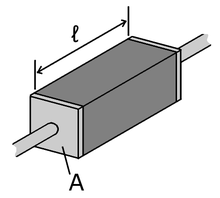
Удельное сопротивление ρ – скалярная физическая величина, численно равная сопротивлению однородного цилиндрического проводника единичной длины и единичной площади сечения (рисунок 1). При расчетах это значение выбирается из таблицы.

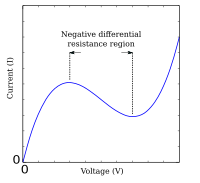
Сопротивление проводника R зависит от внешнего фактора – температуры T, но для разных групп веществ эта зависимость имеет различные зависимости. Так, при снижении температуры металлов их сопротивление снижается (то есть способность проводить ток увеличивается). Если температура металла достигает низких значений, он переходит в состояние так называемой свехрпроводимости и его сопротивление R стремится к 0. Поведение полупроводников под воздействием температур обратное – при снижении температуры T сопротивление R растет, а при его росте наоборот падает (рисунок 2).

Закон Ома
В 1826 году немецкий физик Георг Ом открыл важный в электронике закон, названный впоследствии его фамилией. Закон Ома определяет количественную зависимость между электрическим током и свойствами проводника, характеризующими его способность противостоять электрическому току.
Существует несколько интерпретаций закона Ома.
Закон Ома для участка цепи (рисунок 3) определяет величину электрического тока I в проводнике как отношение напряжения на концах проводника U и его сопротивления R

Интерпретировать закон Ома для участка цепи можно следующим образом: если к концам проводника сопротивлением R = 1 Ом приложено напряжение U = 1 В, тогда величина тока I в проводнике будет равна 1 А
![]()
На представленном выше простом примере разберем физическую интерпретацию закона Ома, используя аналогию электрического тока и воды. В качестве аналога проводника электрического тока возьмем воронку, сужение в которой возникает из-за наличие в проводнике сопротивления R (рисунок 4). Пусть в воронку из некоторого источника поступает вода, которая просачивается через узкое горлышко. Усилить поток воды на выходе горлышка воронки можно за счет давления на воду, например, силой поршня. В аналогии с электричеством, поршень будет являться аналогом напряжения – чем сильнее на воду давит поршень (то есть чем больше значение напряжения), тем сильнее будет поток воды на выходе из воронки (тем больше будет значение силы тока).

Закон Ома может быть применен не всегда, а лишь в ограниченном числе случаев. Так закон Ома «не работает» при расчете напряжения и тока в полупроводниковых или электровакуумных приборов, содержащих нелинейные элементы. В этом случае зависимость тока и напряжения можно определить только с помощью построение так называемой вольтамперной характеристики (ВАХ). К категории нелинейных элементов относятся все без исключения полупроводниковые приборы (диоды, транзисторы, стабилитроны, тиристоры, варикапы и т.д.), а также электронные лампы.
Проводимость
Величина обратная сопротивлению, называется проводимостью:
G = 1/R.
Единица проводимости называется сименс (См): G, (g) = 1/Ом = См.
#1. Формула закона для участка цепи Ома
I = U/R
R = I/U
I = R/U

#2. Найдите сопротивление участка цепи использую закон Ома, если к концам проводника приложено U = 12 В, и в нем протекает ток I = 6 А.
2 Ом.
72 Ом.
5 Ом.
Закон Ома гласит I=U/R, следовательно R = U/I = 12/6 = 2 Ом.
#3. В чем измеряется удельное сопротивление?
Ом*м
Ом*мм
Ом
#4. Сопротивление участка цепи равно 10 Ом. Найдите проводимость участка.
0,1 См.
5 См.
10 См.
Величина обратная сопротивлению, называется проводимостью:
G = 1/R.
Так как сопротивление участка цепи R = 10 Ом, следовательно G = 1/10 = 0,1 См.
Результат
Отлично!
Попытайтесь снова(
Почему медь проводит электричество лучше, чем вода? Прочитав эту статью, вы больше не будете задавать себе больше этот вопрос. Далее мы обсудим электропроводность и рассмотрим формулы, которые описывают это понятие. Наконец, вы можете проверить свои знания на двух примерах.
Простое объяснение.
Электропроводность — это физическая величина, которая описывает насколько хорошо определенный материал проводит электричество.
Формулы
Существует три различных формульных обозначения удельной электропроводности σ (греч. сигма), k (каппа) и γ (гамма). В дальнейшем мы будем использовать σ. Формула электропроводности, также называемой удельной электропроводностью, описывается формулой:
σ = 1 / ρ .
Здесь ρ называется удельным сопротивлением. Вы можете рассчитать электрическое сопротивление R проводника с учетом его параметров следующим образом: R = ( ρ * l ) / S .
Таким образом, сопротивление R равно удельному сопротивлению ρ , умноженному на длину проводника l, деленному на площадь поперечного сечения S. Если теперь вы хотите выразить эту формулу через удельную электропроводность σ = 1 / ρ , полезно знать, что электрическая проводимость G проводника выражается следующим образом: G = 1 / R .
Если в верхнюю формулу подставить удельную электропроводность σ и электрическую проводимость G, то получится следующее: 1 / G = ( 1 / σ ) * ( l / S ) .
Путем дальнейшего преобразования можно получить выражение: G = σ * S / l .
С помощью электропроводности можно также описать важную зависимость между плотностью электрического тока и напряженностью электрического поля с помощью выражения: J = σ * E .
Единица измерения
Единицей удельной электропроводности σ в СИ является: [ σ ] = 1 См/м ( Сименс на метр ).
Эти единицы определяются по формуле G = σ * S / l . Если решить эту формулу в соответствии с σ, то получим σ = G * l / S .
Единица измерения электрической проводимости G задается как: [ G ] = 1 / σ = 1 См ( Сименс, международное обозначение: S ).
Если теперь ввести в формулу все единицы измерения, то получится:
[ σ ] = 1 См * 1 м / м2 = 1 См / м .
Вы также будете чаще использовать единицы измерения См / см , м / Ом * мм2 или См * м / мм2 . Вы можете преобразовать отдельные измеряемые переменные так: См / см = См / 10-2 м и так: м / Ом * мм2 = См * м / мм2 = См * м / 10-3 м * 10-3 м = 106 См / м .
Электропроводность металлов
В зависимости от количества свободно перемещающихся электронов один материал проводит лучше, чем другой. В принципе, любой материал является проводящим, но в изоляторах, например, протекающий электрический ток ничтожно мал, поэтому здесь мы говорим о непроводниках.
В металлических связях валентные электроны, т.е. крайние электроны в атоме, свободно подвижны. Они расположены в так называемой полосе проводимости. Находящиеся там электроны образуют так называемый электронный газ. Соответственно, металлы являются сравнительно хорошими проводниками. Если теперь подать электрическое напряжение на металл, валентные электроны медленно движутся к положительному полюсу, потому что он их притягивает.

На рисунке 1 видно, что некоторые электроны не могут быть притянуты непосредственно к положительному полюсу, потому что на пути стоит, так сказать, твердое атомное ядро. Там они замедляются и в некоторой степени отклоняются. Именно поэтому электроны не могут ускоряться в металле бесконечно, и именно так возникает удельное сопротивление или электропроводность.
Теперь вы также можете измерить удельную электропроводность в металле с помощью следующей формулы: σ = ( n * e2 * τ ) / m .
В этой формуле n означает число электронов, e — заряд электрона, m — массу электрона, а τ — среднее время полета электрона между двумя столкновениями.
Таблица удельной электропроводности
Для большинства веществ уже известны значения удельной электропроводности. Некоторые из них вы можете найти в следующей таблице ниже. Все значения в этой таблице действительны для комнатной температуры, т.е. 25°C.
| Вещество | Удельная электропроводность в См / м |
| Серебро | 62 · 106 |
| Медь | 58 · 106 |
| Золото | 45,2 · 106 |
| Алюминий | 37,7 · 106 |
| Вольфрам | 19 · 106 |
| Латунь | 15,5 · 106 |
| Железо | 9,93 · 106 |
| Нержавеющая сталь (WNr. 1,4301) | 1,36 · 106 |
| Германий (легирование <10-9) | 2 |
| Кремний (легирование <10-12) | 0,5 · 10-3 |
| Морская вода | примерно 5 |
| Водопроводная вода | примерно 0,05 |
| Дистиллированная вода | 5 · 10-6 |
| Изолятор | обычно <10-8 |
Удельная электропроводность сильно зависит от температуры, поэтому указанные значения применимы только при 25°C. При повышении температуры вибрация решетки в веществе становится выше. Это нарушает поток электронов, и поэтому электропроводность уменьшается с ростом температуры.
Из таблицы видно, что медь имеет вторую по величине электропроводность, поэтому медные кабели очень часто используются в электротехнике. Серебро обладает еще более высокой проводимостью, но стоит намного дороже меди.
Интересно также сравнение между морской и дистиллированной водой. Здесь электропроводность возникает благодаря растворенным в воде ионам. Морская вода имеет очень высокую долю соли, которая растворяется в воде. Эти ионы передают электрический ток. В дистиллированной воде нет растворенных ионов, поэтому в ней практически не может протекать электрический ток. Поэтому электропроводность морской воды намного выше, чем дистиллированной.
Примеры задач
Для более детального рассмотрения приведём два примера расчетов.
Задача 1.
В первой задаче представьте, что у вас есть провод длиной 2 м с поперечным сечением 0,5 мм2. Электрическое сопротивление провода при комнатной температуре составляет 106 мОм. Из какого материала изготовлен провод?
Решение.
Решение данной задачи можно найти с помощью формулы: R = ( 1 / σ ) * ( l / S ). Из этой формулы найдём σ = l / ( S * R ) .
Теперь вы можете вставить заданные значения, убедившись, что вы перевели сечение в м2.
σ = l / ( S * R ) = 2 м / ( ( 0,5 * 10-6 м2 ) * ( 1 / 106 * 10-3 Ом ) ) = 37, 7 * 106 См / м .
Наконец, вы ищите в таблице, какой материал имеет удельную электропроводность σ = 37, 7 * 106 См / м и приходите к выводу, что провод сделан из алюминия.
Задача 2.
В задаче 2 вам дано только удельное сопротивление образца с 735 * 10-9 Ом * м. Из какого материла изготовлен образец?
Решение.
Вы можете использовать формулу σ = 1 / ρ для расчёта удельной электропроводности. После подстановки значений в эту формулу вы получите: σ = 1 / ρ = 1 / 735 * 10-9 Ом * м = 1,36 * 106 См / м .
Если вы снова заглянете в таблицу, то обнаружите, что образец должен быть изготовлен из нержавеющей стали.
Последовательное
и параллельное соединения в электротехнике —
два основных способа соединения
элементовэлектрической
цепи.
При последовательном соединении все
элементы связаны друг с другом так, что
включающий их участок цепи не имеет ни
одного узла.
При параллельном соединении все входящие
в цепь элементы объединены двумяузлами и
не имеют связей с другими узлами, если
это не противоречит условию.
При последовательном
соединении проводников сила тока во
всех проводниках одинакова.
При параллельном
соединении падение напряжения между
двумя узлами, объединяющими элементы
цепи, одинаково для всех элементов. При
этом величина, обратная общему
сопротивлению цепи, равна сумме величин,
обратных сопротивлениям параллельно
включенных проводников.
При
последовательном соединении проводников
сила тока в любых частях цепи одна и та
же: ![]()
Полное
напряжение в цепи при последовательном
соединении, или напряжение на полюсах
источника тока, равно сумме напряжений
на отдельных участках цепи: ![]()
![]()
![]() .
.
Параллельное соединение
Сила
тока в неразветвленной части цепи равна
сумме сил токов в отдельных параллельно
соединённых проводниках: ![]()
Напряжение
на участках цепи АВ и на концах всех
параллельно соединённых проводников
одно и то же: ![]()
Резистор
При
параллельном соединении резисторов
складываются величины, обратно
пропорциональные сопротивлению (то
есть общая проводимость ![]() складывается
складывается
из проводимостей каждого резистора ![]() )
)
![]()
Электри́ческое
сопротивле́ние —
физическая величина, характеризующая
свойства проводника препятствовать
прохождению электрического
тока и
равная отношению напряжения на
концах проводника к силе
тока,
протекающего по нему[1].
Сопротивление для цепей переменного
тока и для переменных электромагнитных
полей описывается понятиямиимпеданса и волнового
сопротивления. Сопротивлением (резистором)
также называют радиодеталь, предназначенную
для введения в электрические цепи
активного сопротивления.
Сопротивление
(часто обозначается буквой R или r)
считается, в определённых пределах,
постоянной величиной для данного
проводника; её можно рассчитать как
![]()
где
R —
сопротивление;
U — разность
электрических потенциалов на
концах проводника;
I — сила
тока,
протекающего между концами проводника
под действием разности потенциалов.
Электри́ческая
проводи́мость (электропроводность,
проводимость) — способность тела
проводить электрический
ток,
а такжефизическая
величина,
характеризующая эту способность и
обратная электрическому
сопротивлению.
В СИ единицей
измеренияэлектрической
проводимости является сименс (называемая
также в некоторых странах Мо)[1].
Удельной
проводимостью (удельной электропроводностью)
называют меру
способности вещества проводить электрический
ток.
Согласно закону
Ома в
линейном изотропном веществе
удельная проводимость является
коэффициентом пропорциональности
между плотностью
возникающего токаи величиной
электрического поля в
среде:
![]()
где
-
 —удельная
проводимость, -
 —вектор плотности
тока, -
 —вектор напряжённости
электрического поля.
Соседние файлы в предмете [НЕСОРТИРОВАННОЕ]
- #
- #
- #
- #
- #
- #
- #
- #
- #
- #
- #
This article is about specific applications of conductivity and resistivity in electrical elements. For other types of conductivity, see Conductivity. For electrical conductivity in general, see Electrical resistivity and conductivity.
«Resistive» redirects here. For the term used when referring to touchscreens, see Resistive touchscreen.
The electrical resistance of an object is a measure of its opposition to the flow of electric current. Its reciprocal quantity is electrical conductance, measuring the ease with which an electric current passes. Electrical resistance shares some conceptual parallels with mechanical friction. The SI unit of electrical resistance is the ohm (Ω), while electrical conductance is measured in siemens (S) (formerly called the ‘mho’ and then represented by ℧).
The resistance of an object depends in large part on the material it is made of. Objects made of electrical insulators like rubber tend to have very high resistance and low conductance, while objects made of electrical conductors like metals tend to have very low resistance and high conductance. This relationship is quantified by resistivity or conductivity. The nature of a material is not the only factor in resistance and conductance, however; it also depends on the size and shape of an object because these properties are extensive rather than intensive. For example, a wire’s resistance is higher if it is long and thin, and lower if it is short and thick. All objects resist electrical current, except for superconductors, which have a resistance of zero.
The resistance R of an object is defined as the ratio of voltage V across it to current I through it, while the conductance G is the reciprocal:

For a wide variety of materials and conditions, V and I are directly proportional to each other, and therefore R and G are constants (although they will depend on the size and shape of the object, the material it is made of, and other factors like temperature or strain). This proportionality is called Ohm’s law, and materials that satisfy it are called ohmic materials.
In other cases, such as a transformer, diode or battery, V and I are not directly proportional. The ratio V/I is sometimes still useful, and is referred to as a chordal resistance or static resistance,[1][2] since it corresponds to the inverse slope of a chord between the origin and an I–V curve. In other situations, the derivative  may be most useful; this is called the differential resistance.
Introduction[edit]

The hydraulic analogy compares electric current flowing through circuits to water flowing through pipes. When a pipe (left) is filled with hair (right), it takes a larger pressure to achieve the same flow of water. Pushing electric current through a large resistance is like pushing water through a pipe clogged with hair: It requires a larger push (electromotive force) to drive the same flow (electric current).
In the hydraulic analogy, current flowing through a wire (or resistor) is like water flowing through a pipe, and the voltage drop across the wire is like the pressure drop that pushes water through the pipe. Conductance is proportional to how much flow occurs for a given pressure, and resistance is proportional to how much pressure is required to achieve a given flow.
The voltage drop (i.e., difference between voltages on one side of the resistor and the other), not the voltage itself, provides the driving force pushing current through a resistor. In hydraulics, it is similar: the pressure difference between two sides of a pipe, not the pressure itself, determines the flow through it. For example, there may be a large water pressure above the pipe, which tries to push water down through the pipe. But there may be an equally large water pressure below the pipe, which tries to push water back up through the pipe. If these pressures are equal, no water flows. (In the image at right, the water pressure below the pipe is zero.)
The resistance and conductance of a wire, resistor, or other element is mostly determined by two properties:
- geometry (shape), and
- material
Geometry is important because it is more difficult to push water through a long, narrow pipe than a wide, short pipe. In the same way, a long, thin copper wire has higher resistance (lower conductance) than a short, thick copper wire.
Materials are important as well. A pipe filled with hair restricts the flow of water more than a clean pipe of the same shape and size. Similarly, electrons can flow freely and easily through a copper wire, but cannot flow as easily through a steel wire of the same shape and size, and they essentially cannot flow at all through an insulator like rubber, regardless of its shape. The difference between copper, steel, and rubber is related to their microscopic structure and electron configuration, and is quantified by a property called resistivity.
In addition to geometry and material, there are various other factors that influence resistance and conductance, such as temperature; see below.
Conductors and resistors[edit]
![]()
Substances in which electricity can flow are called conductors. A piece of conducting material of a particular resistance meant for use in a circuit is called a resistor. Conductors are made of high-conductivity materials such as metals, in particular copper and aluminium. Resistors, on the other hand, are made of a wide variety of materials depending on factors such as the desired resistance, amount of energy that it needs to dissipate, precision, and costs.
Ohm’s law[edit]

For many materials, the current I through the material is proportional to the voltage V applied across it:

over a wide range of voltages and currents. Therefore, the resistance and conductance of objects or electronic components made of these materials is constant. This relationship is called Ohm’s law, and materials which obey it are called ohmic materials. Examples of ohmic components are wires and resistors. The current–voltage graph of an ohmic device consists of a straight line through the origin with positive slope.
Other components and materials used in electronics do not obey Ohm’s law; the current is not proportional to the voltage, so the resistance varies with the voltage and current through them. These are called nonlinear or non-ohmic. Examples include diodes and fluorescent lamps. The current-voltage curve of a nonohmic device is a curved line.
Relation to resistivity and conductivity[edit]
A piece of resistive material with electrical contacts on both ends.
The resistance of a given object depends primarily on two factors: what material it is made of, and its shape. For a given material, the resistance is inversely proportional to the cross-sectional area; for example, a thick copper wire has lower resistance than an otherwise-identical thin copper wire. Also, for a given material, the resistance is proportional to the length; for example, a long copper wire has higher resistance than an otherwise-identical short copper wire. The resistance R and conductance G of a conductor of uniform cross section, therefore, can be computed as
![{displaystyle {begin{aligned}R&=rho {frac {ell }{A}},\[5pt]G&=sigma {frac {A}{ell }},.end{aligned}}}](https://wikimedia.org/api/rest_v1/media/math/render/svg/b24667605c2703efd09de736ebc63d30be931418)
where  is the length of the conductor, measured in metres (m), A is the cross-sectional area of the conductor measured in square metres (m2), σ (sigma) is the electrical conductivity measured in siemens per meter (S·m−1), and ρ (rho) is the electrical resistivity (also called specific electrical resistance) of the material, measured in ohm-metres (Ω·m). The resistivity and conductivity are proportionality constants, and therefore depend only on the material the wire is made of, not the geometry of the wire. Resistivity and conductivity are reciprocals:
  . Resistivity is a measure of the material’s ability to oppose electric current.
This formula is not exact, as it assumes the current density is totally uniform in the conductor, which is not always true in practical situations. However, this formula still provides a good approximation for long thin conductors such as wires.
Another situation for which this formula is not exact is with alternating current (AC), because the skin effect inhibits current flow near the center of the conductor. For this reason, the geometrical cross-section is different from the effective cross-section in which current actually flows, so resistance is higher than expected. Similarly, if two conductors near each other carry AC current, their resistances increase due to the proximity effect. At commercial power frequency, these effects are significant for large conductors carrying large currents, such as busbars in an electrical substation,[3] or large power cables carrying more than a few hundred amperes.
The resistivity of different materials varies by an enormous amount: For example, the conductivity of teflon is about 1030 times lower than the conductivity of copper. Loosely speaking, this is because metals have large numbers of «delocalized» electrons that are not stuck in any one place, so they are free to move across large distances. In an insulator, such as Teflon, each electron is tightly bound to a single molecule so a great force is required to pull it away. Semiconductors lie between these two extremes. More details can be found in the article: Electrical resistivity and conductivity. For the case of electrolyte solutions, see the article: Conductivity (electrolytic).
Resistivity varies with temperature. In semiconductors, resistivity also changes when exposed to light. See below.
Measurement[edit]

An instrument for measuring resistance is called an ohmmeter. Simple ohmmeters cannot measure low resistances accurately because the resistance of their measuring leads causes a voltage drop that interferes with the measurement, so more accurate devices use four-terminal sensing.
Typical values[edit]
| Component | Resistance (Ω) |
|---|---|
| 1 meter of copper wire with 1 mm diameter | 0.02[a] |
| 1 km overhead power line (typical) | 0.03[5] |
| AA battery (typical internal resistance) | 0.1[b] |
| Incandescent light bulb filament (typical) | 200–1000[c] |
| Human body | 1000–100,000[d] |
Static and differential resistance[edit]
Many electrical elements, such as diodes and batteries do not satisfy Ohm’s law. These are called non-ohmic or non-linear, and their current–voltage curves are not straight lines through the origin.
Resistance and conductance can still be defined for non-ohmic elements. However, unlike ohmic resistance, non-linear resistance is not constant but varies with the voltage or current through the device; i.e., its operating point. There are two types of resistance:[1][2]
- Static resistance
- This corresponds to the usual definition of resistance; the voltage divided by the current

It is the slope of the line (chord) from the origin through the point on the curve. Static resistance determines the power dissipation in an electrical component. Points on the current–voltage curve located in the 2nd or 4th quadrants, for which the slope of the chordal line is negative, have negative static resistance. Passive devices, which have no source of energy, cannot have negative static resistance. However active devices such as transistors or op-amps can synthesize negative static resistance with feedback, and it is used in some circuits such as gyrators.
- Differential resistance
- Differential resistance is the derivative of the voltage with respect to the current; the slope of the current–voltage curve at a point
If the current–voltage curve is nonmonotonic (with peaks and troughs), the curve has a negative slope in some regions—so in these regions the device has negative differential resistance. Devices with negative differential resistance can amplify a signal applied to them, and are used to make amplifiers and oscillators. These include tunnel diodes, Gunn diodes, IMPATT diodes, magnetron tubes, and unijunction transistors.
Also called chordal or DC resistance

Also called dynamic, incremental, or small-signal resistance

AC circuits[edit]
Impedance and admittance[edit]

The voltage (red) and current (blue) versus time (horizontal axis) for a capacitor (top) and inductor (bottom). Since the amplitude of the current and voltage sinusoids are the same, the absolute value of impedance is 1 for both the capacitor and the inductor (in whatever units the graph is using). On the other hand, the phase difference between current and voltage is −90° for the capacitor; therefore, the complex phase of the impedance of the capacitor is −90°. Similarly, the phase difference between current and voltage is +90° for the inductor; therefore, the complex phase of the impedance of the inductor is +90°.
When an alternating current flows through a circuit, the relation between current and voltage across a circuit element is characterized not only by the ratio of their magnitudes, but also the difference in their phases. For example, in an ideal resistor, the moment when the voltage reaches its maximum, the current also reaches its maximum (current and voltage are oscillating in phase). But for a capacitor or inductor, the maximum current flow occurs as the voltage passes through zero and vice versa (current and voltage are oscillating 90° out of phase, see image below). Complex numbers are used to keep track of both the phase and magnitude of current and voltage:

where:
The impedance and admittance may be expressed as complex numbers that can be broken into real and imaginary parts:

where R is resistance, G is conductance, X is reactance, and B is susceptance. These lead to the complex number identities

which are true in all cases, whereas  is only true in the special cases of either DC or reactance-free current.
The complex angle  is the phase difference between the voltage and current passing through a component with impedance Z. For capacitors and inductors, this angle is exactly -90° or +90°, respectively, and X and B are nonzero. Ideal resistors have an angle of 0°, since X is zero (and hence B also), and Z and Y reduce to R and G respectively. In general, AC systems are designed to keep the phase angle close to 0° as much as possible, since it reduces the reactive power, which does no useful work at a load. In a simple case with an inductive load (causing the phase to increase), a capacitor may be added for compensation at one frequency, since the capacitor’s phase shift is negative, bringing the total impedance phase closer to 0° again.
Y is the reciprocal of Z ( ) for all circuits, just as
  for DC circuits containing only resistors, or AC circuits for which either the reactance or susceptance happens to be zero (X or B = 0, respectively) (if one is zero, then for realistic systems both must be zero).
Frequency dependence[edit]
A key feature of AC circuits is that the resistance and conductance can be frequency-dependent, a phenomenon known as the universal dielectric response.[8] One reason, mentioned above is the skin effect (and the related proximity effect). Another reason is that the resistivity itself may depend on frequency (see Drude model, deep-level traps, resonant frequency, Kramers–Kronig relations, etc.)
Energy dissipation and Joule heating[edit]

Resistors (and other elements with resistance) oppose the flow of electric current; therefore, electrical energy is required to push current through the resistance. This electrical energy is dissipated, heating the resistor in the process. This is called Joule heating (after James Prescott Joule), also called ohmic heating or resistive heating.
The dissipation of electrical energy is often undesired, particularly in the case of transmission losses in power lines. High voltage transmission helps reduce the losses by reducing the current for a given power.
On the other hand, Joule heating is sometimes useful, for example in electric stoves and other electric heaters (also called resistive heaters). As another example, incandescent lamps rely on Joule heating: the filament is heated to such a high temperature that it glows «white hot» with thermal radiation (also called incandescence).
The formula for Joule heating is:

where P is the power (energy per unit time) converted from electrical energy to thermal energy, R is the resistance, and I is the current through the resistor.
Dependence on other conditions[edit]
Temperature dependence[edit]
Near room temperature, the resistivity of metals typically increases as temperature is increased, while the resistivity of semiconductors typically decreases as temperature is increased. The resistivity of insulators and electrolytes may increase or decrease depending on the system. For the detailed behavior and explanation, see Electrical resistivity and conductivity.
As a consequence, the resistance of wires, resistors, and other components often change with temperature. This effect may be undesired, causing an electronic circuit to malfunction at extreme temperatures. In some cases, however, the effect is put to good use. When temperature-dependent resistance of a component is used purposefully, the component is called a resistance thermometer or thermistor. (A resistance thermometer is made of metal, usually platinum, while a thermistor is made of ceramic or polymer.)
Resistance thermometers and thermistors are generally used in two ways. First, they can be used as thermometers: by measuring the resistance, the temperature of the environment can be inferred. Second, they can be used in conjunction with Joule heating (also called self-heating): if a large current is running through the resistor, the resistor’s temperature rises and therefore its resistance changes. Therefore, these components can be used in a circuit-protection role similar to fuses, or for feedback in circuits, or for many other purposes. In general, self-heating can turn a resistor into a nonlinear and hysteretic circuit element. For more details see Thermistor#Self-heating effects.
If the temperature T does not vary too much, a linear approximation is typically used:
![{displaystyle R(T)=R_{0}[1+alpha (T-T_{0})]}](https://wikimedia.org/api/rest_v1/media/math/render/svg/5b6622ab35566bd32d26736effa752dc8ace798d)
where  is called the temperature coefficient of resistance,
  is a fixed reference temperature (usually room temperature), and
  is the resistance at temperature . The parameter is an empirical parameter fitted from measurement data. Because the linear approximation is only an approximation, is different for different reference temperatures. For this reason it is usual to specify the temperature that was measured at with a suffix, such as
  , and the relationship only holds in a range of temperatures around the reference.[9]
The temperature coefficient is typically +3×10⁻³ K−1 to +6×10⁻³ K−1 for metals near room temperature. It is usually negative for semiconductors and insulators, with highly variable magnitude.[e]
Strain dependence[edit]
Just as the resistance of a conductor depends upon temperature, the resistance of a conductor depends upon strain.[10] By placing a conductor under tension (a form of stress that leads to strain in the form of stretching of the conductor), the length of the section of conductor under tension increases and its cross-sectional area decreases. Both these effects contribute to increasing the resistance of the strained section of conductor. Under compression (strain in the opposite direction), the resistance of the strained section of conductor decreases. See the discussion on strain gauges for details about devices constructed to take advantage of this effect.
Light illumination dependence[edit]
Some resistors, particularly those made from semiconductors, exhibit photoconductivity, meaning that their resistance changes when light is shining on them. Therefore, they are called photoresistors (or light dependent resistors). These are a common type of light detector.
Superconductivity[edit]
Superconductors are materials that have exactly zero resistance and infinite conductance, because they can have V = 0 and I ≠ 0. This also means there is no joule heating, or in other words no dissipation of electrical energy. Therefore, if superconductive wire is made into a closed loop, current flows around the loop forever. Superconductors require cooling to temperatures near 4 K with liquid helium for most metallic superconductors like niobium–tin alloys, or cooling to temperatures near 77 K with liquid nitrogen for the expensive, brittle and delicate ceramic high temperature superconductors.
Nevertheless, there are many technological applications of superconductivity, including superconducting magnets.
See also[edit]
- Conductance quantum
- Von Klitzing constant (its reciprocal)
- Electrical measurements
- Contact resistance
- Electrical resistivity and conductivity for more information about the physical mechanisms for conduction in materials.
- Johnson–Nyquist noise
- Quantum Hall effect, a standard for high-accuracy resistance measurements.
- Resistor
- RKM code
- Series and parallel circuits
- Sheet resistance
- SI electromagnetism units
- Thermal resistance
- Voltage divider
- Voltage drop
Footnotes[edit]
- ^ The resistivity of copper is about 1.7×10⁻⁸ Ω⋅m.[4]
- ^ For a fresh Energizer E91 AA alkaline battery, the internal resistance varies from 0.9 Ω at −40 °C, to 0.1 Ω at +40 °C.[6]
- ^ A 60 W light bulb (in the USA, with 120 V mains electricity) draws RMS current 60 W/120 V = 500 mA, so its resistance is 120 V/500 mA = 240 Ω. The resistance of a 60 W light bulb in Europe (230 V mains) is 900 Ω. The resistance of a filament is temperature-dependent; these values are for when the filament is already heated up and the light is already glowing.
- ^ 100 kΩ for dry skin contact, 1 kΩ for wet or broken skin contact. High voltage breaks down the skin, lowering resistance to 500 Ω. Other factors and conditions are relevant as well. For more details, see the electric shock article, and NIOSH 98-131.[7]
- ^ See Electrical resistivity and conductivity for a table. The temperature coefficient of resistivity is similar but not identical to the temperature coefficient of resistance. The small difference is due to thermal expansion changing the dimensions of the resistor.
References[edit]
- ^ a b Brown, Forbes T. (2006). Engineering System Dynamics: A Unified Graph-Centered Approach (2nd ed.). Boca Raton, Florida: CRC Press. p. 43. ISBN 978-0-8493-9648-9.
- ^ a b Kaiser, Kenneth L. (2004). Electromagnetic Compatibility Handbook. Boca Raton, Florida: CRC Press. pp. 13–52. ISBN 978-0-8493-2087-3.
- ^ Fink & Beaty (1923). «Standard Handbook for Electrical Engineers». Nature (11th ed.). 111 (2788): 17–19. Bibcode:1923Natur.111..458R. doi:10.1038/111458a0. hdl:2027/mdp.39015065357108. S2CID 26358546.
- ^ Cutnell, John D.; Johnson, Kenneth W. (1992). Physics (2nd ed.). New York: Wiley. p. 559. ISBN 978-0-471-52919-4.
- ^ McDonald, John D. (2016). Electric Power Substations Engineering (2nd ed.). Boca Raton, Florida: CRC Press. pp. 363ff. ISBN 978-1-4200-0731-2.
- ^ Battery internal resistance (PDF) (Report). Energizer Corp.
- ^ «Worker Deaths by Electrocution» (PDF). National Institute for Occupational Safety and Health. Publication No. 98-131. Retrieved 2 November 2014.
- ^ Zhai, Chongpu; Gan, Yixiang; Hanaor, Dorian; Proust, Gwénaëlle (2018). «Stress-dependent electrical transport and its universal scaling in granular materials». Extreme Mechanics Letters. 22: 83–88. arXiv:1712.05938. doi:10.1016/j.eml.2018.05.005. S2CID 51912472.
- ^ Ward, M.R. (1971). Electrical Engineering Science. McGraw-Hill. pp. 36–40.
- ^ Meyer, Sebastian; et al. (2022), «Characterization of the deformation state of magnesium by electrical resistance», Volume 215, Scripta Materialia, vol. 215, p. 114712, doi:10.1016/j.scriptamat.2022.114712, S2CID 247959452
External links[edit]
- «Resistance calculator». Vehicular Electronics Laboratory. Clemson University. Archived from the original on 11 July 2010.
- «Electron conductance models using maximal entropy random walks». wolfram.com. Wolfram Demonstrantions Project.
Проводимость
Добавлено 4 января 2021 в 17:10
Когда учащиеся впервые видят формулу общего параллельного сопротивления, возникает естественный вопрос: «Откуда эта штука?». Это действительно странная арифметика, и ее происхождение заслуживает хорошего объяснения.
В чем разница между сопротивлением и проводимостью?
Сопротивление, по определению, является мерой «трения», которое компонент представляет для прохождения через него тока. Сопротивление обозначается заглавной буквой «R» и измеряется в единицах «Ом». Однако мы также можем думать об этом электрическом свойстве с обратной ему точки зрения: насколько легко току течь через компонент, а не насколько трудно.
Если сопротивление – это термин, которое мы используем для обозначения меры того, насколько трудно току течь, то хорошим термином, чтобы выразить, насколько легко ток течет, будет проводимость. Математически проводимость – это величина, обратная сопротивлению:
[проводимость = frac{1}{сопротивление}]
Чем больше сопротивление, тем меньше проводимость; и наоборот.
Это должно быть интуитивно понятно, потому что сопротивление и проводимость – противоположные способы обозначения одного и того же важного электрического свойства.
Если сравнивать сопротивления двух компонентов и обнаружится, что компонент «A» имеет сопротивление вдвое меньше сопротивления компонента «B», то в качестве альтернативы мы могли бы выразить это соотношение, сказав, что компонент «A» в два раза более проводящий, чем компонент «B». Если компонент «A» имеет сопротивление, равное только одной трети от сопротивления компонента «B», то мы можем сказать, что он в три раза более проводящий, чем компонент «B», и так далее.
Единица измерения проводимости
В продолжение этой идеи были придуманы символ и единица измерения проводимости. Символ представляет собой заглавную букву «G», а единицей измерения был mho, что означает «ohm» (ом), написанное в обратном порядке (вы думали, что у электронщиков нет чувства юмора?).
Несмотря на свою уместность, единицы измерения mho в последующие годы были заменены единицей Сименс (сокращенно «См», или, в англоязычной литературе, «S»). Это решение об изменении названий единиц измерения напоминает изменение единицы измерения температуры в градусах стоградусной шкалы (degrees centigrade – от латинских слов «centum», т.е. «сто», и «gradus») на градусы Цельсия (degrees Celsius) или изменение единицы измерения частоты c.p.s. (циклов в секунду) в герцы. Если вы ищете здесь какой-то шаблон переименования, то Сименс, Цельсий и Герц – это фамилии известных ученых, имена которых, к сожалению, о природе единиц говорят нам меньше, чем их первоначальные обозначения.
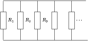
Возвращаясь к нашему примеру с параллельной схемой, мы должны быть в состоянии увидеть, что несколько путей (ветвей) для тока уменьшают общее сопротивление всей цепи, поскольку ток может легче проходить через всю цепь из нескольких ветвей, чем через любую из них отдельно. Что касается сопротивления, дополнительные ветви приводят к меньшему общему значению (ток встречает меньшее сопротивление). Однако с точки зрения проводимости дополнительные ветви приводят к большему общему значению (ток протекает с большей проводимостью).
Общее сопротивление параллельной цепи
Общее сопротивление параллельной цепи меньше, чем любое из сопротивлений отдельных ветвей, потому что параллельные резисторы вместе «сопротивляются» меньше, чем по отдельности:
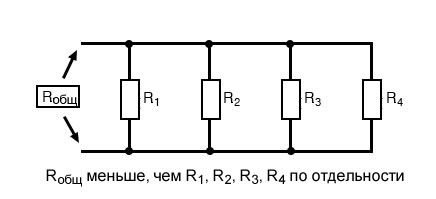
Общая проводимость параллельной цепи
Общая проводимость параллельной цепи больше, чем проводимость любой из отдельных ветвей, потому что параллельные резисторы «проводят» вместе лучше, чем по отдельности:
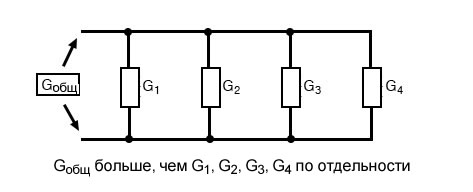
Чтобы быть более точным, полная проводимость в параллельной цепи равна сумме отдельных проводимостей:
[G_{общ} = G_1 + G_2 + G_3 + G_4]
Если мы знаем, что проводимость – это не что иное, как математическая величина, обратная (1/x) сопротивлению, мы можем перевести каждый член приведенной выше формулы в сопротивление, подставив величину, обратную каждой соответствующей проводимости:
[frac{1}{R_{общ}} = frac{1}{R_{1}} + frac{1}{R_{2}} + frac{1}{R_{3}} + frac{1}{R_{4}}]
Решая приведенное выше уравнение для полного сопротивления (вместо значения, обратного общему сопротивлению), мы получим следующую формулу:
[R_{общ} = frac{1}{frac{1}{R_{1}} + frac{1}{R_{2}} + frac{1}{R_{3}} + frac{1}{R_{4}}}]
Итак, мы, наконец, пришли к нашей загадочной формуле сопротивления! Проводимость (G) редко используется в качестве практического параметра, поэтому при анализе параллельных цепей часто используется приведенная выше формула.
Резюме
- Проводимость – параметр, противоположный сопротивлению: это мера того, насколько легко электрический ток проходит через что-то.
- Проводимость обозначается буквой «G» и измеряется в сименсах (сокр. См).
- Математически проводимость равна величине, обратной сопротивлению: G = 1/R.
Теги
ОбучениеПараллельная цепьПроводимостьСопротивление