
A binary clock might use LEDs to express binary values. In this clock, each column of LEDs shows a binary-coded decimal numeral of the traditional sexagesimal time.
In computing and electronic systems, binary-coded decimal (BCD) is a class of binary encodings of decimal numbers where each digit is represented by a fixed number of bits, usually four or eight. Sometimes, special bit patterns are used for a sign or other indications (e.g. error or overflow).
In byte-oriented systems (i.e. most modern computers), the term unpacked BCD[1] usually implies a full byte for each digit (often including a sign), whereas packed BCD typically encodes two digits within a single byte by taking advantage of the fact that four bits are enough to represent the range 0 to 9. The precise 4-bit encoding, however, may vary for technical reasons (e.g. Excess-3).
The ten states representing a BCD digit are sometimes called tetrades[2][3] (the nibble typically needed to hold them is also known as a tetrade) while the unused, don’t care-states are named pseudo-tetrad(e)s [de],[4][5][6][7][8] pseudo-decimals[3] or pseudo-decimal digits.[9][10][nb 1]
BCD’s main virtue, in comparison to binary positional systems, is its more accurate representation and rounding of decimal quantities, as well as its ease of conversion into conventional human-readable representations. Its principal drawbacks are a slight increase in the complexity of the circuits needed to implement basic arithmetic as well as slightly less dense storage.
BCD was used in many early decimal computers, and is implemented in the instruction set of machines such as the IBM System/360 series and its descendants, Digital Equipment Corporation’s VAX, the Burroughs B1700, and the Motorola 68000-series processors. BCD per se is not as widely used as in the past, and is unavailable or limited in newer instruction sets (e.g., ARM; x86 in long mode). However, decimal fixed-point and decimal floating-point formats are still important and continue to be used in financial, commercial, and industrial computing, where the subtle conversion and fractional rounding errors that are inherent in binary floating point formats cannot be tolerated.[11]
Background[edit]
BCD takes advantage of the fact that any one decimal numeral can be represented by a four-bit pattern. The most obvious way of encoding digits is Natural BCD (NBCD), where each decimal digit is represented by its corresponding four-bit binary value, as shown in the following table. This is also called «8421» encoding.
| Decimal digit | BCD | |||
|---|---|---|---|---|
| 8 | 4 | 2 | 1 | |
| 0 | 0 | 0 | 0 | 0 |
| 1 | 0 | 0 | 0 | 1 |
| 2 | 0 | 0 | 1 | 0 |
| 3 | 0 | 0 | 1 | 1 |
| 4 | 0 | 1 | 0 | 0 |
| 5 | 0 | 1 | 0 | 1 |
| 6 | 0 | 1 | 1 | 0 |
| 7 | 0 | 1 | 1 | 1 |
| 8 | 1 | 0 | 0 | 0 |
| 9 | 1 | 0 | 0 | 1 |
This scheme can also be referred to as Simple Binary-Coded Decimal (SBCD) or BCD 8421, and is the most common encoding.[12] Others include the so-called «4221» and «7421» encoding – named after the weighting used for the bits – and «Excess-3».[13] For example, the BCD digit 6, 0110'b in 8421 notation, is 1100'b in 4221 (two encodings are possible), 0110'b in 7421, while in Excess-3 it is 1001'b ( ).
).
| Bit | Weight | 0 | 1 | 2 | 3 | 4 | 5 | 6 | 7 | 8 | 9 | 10 | 11 | 12 | 13 | 14 | 15 | Comment |
|---|---|---|---|---|---|---|---|---|---|---|---|---|---|---|---|---|---|---|
| 4 | 8 | 0 | 0 | 0 | 0 | 0 | 0 | 0 | 0 | 1 | 1 | 1 | 1 | 1 | 1 | 1 | 1 | Binary |
| 3 | 4 | 0 | 0 | 0 | 0 | 1 | 1 | 1 | 1 | 0 | 0 | 0 | 0 | 1 | 1 | 1 | 1 | |
| 2 | 2 | 0 | 0 | 1 | 1 | 0 | 0 | 1 | 1 | 0 | 0 | 1 | 1 | 0 | 0 | 1 | 1 | |
| 1 | 1 | 0 | 1 | 0 | 1 | 0 | 1 | 0 | 1 | 0 | 1 | 0 | 1 | 0 | 1 | 0 | 1 | |
| Name | 0 | 1 | 2 | 3 | 4 | 5 | 6 | 7 | 8 | 9 | 10 | 11 | 12 | 13 | 14 | 15 | Decimal | |
| 8 4 2 1 (XS-0) | 0 | 1 | 2 | 3 | 4 | 5 | 6 | 7 | 8 | 9 | 10 | 11 | 12 | 13 | 14 | 15 | [14][15][16][17][nb 2] | |
| 7 4 2 1 | 0 | 1 | 2 | 3 | 4 | 5 | 6 | 7 | 8 | 9 | [18][19][20] | |||||||
| Aiken (2 4 2 1) | 0 | 1 | 2 | 3 | 4 | 5 | 6 | 7 | 8 | 9 | [14][15][16][17][nb 3] | |||||||
| Excess-3 (XS-3) | -3 | -2 | -1 | 0 | 1 | 2 | 3 | 4 | 5 | 6 | 7 | 8 | 9 | 10 | 11 | 12 | [14][15][16][17][nb 2] | |
| Excess-6 (XS-6) | -6 | -5 | -4 | -3 | -2 | -1 | 0 | 1 | 2 | 3 | 4 | 5 | 6 | 7 | 8 | 9 | [18][nb 2] | |
| Jump-at-2 (2 4 2 1) | 0 | 1 | 2 | 3 | 4 | 5 | 6 | 7 | 8 | 9 | [16][17] | |||||||
| Jump-at-8 (2 4 2 1) | 0 | 1 | 2 | 3 | 4 | 5 | 6 | 7 | 8 | 9 | [21][22][16][17][nb 4] | |||||||
| 4 2 2 1 (I) | 0 | 1 | 2 | 3 | 4 | 5 | 6 | 7 | 8 | 9 | [16][17] | |||||||
| 4 2 2 1 (II) | 0 | 1 | 2 | 3 | 4 | 5 | 6 | 7 | 8 | 9 | [21][22] | |||||||
| 5 4 2 1 | 0 | 1 | 2 | 3 | 4 | 5 | 6 | 7 | 8 | 9 | [18][14][16][17] | |||||||
| 5 2 2 1 | 0 | 1 | 2 | 3 | 4 | 5 | 6 | 7 | 8 | 9 | [14][16][17] | |||||||
| 5 1 2 1 | 0 | 1 | 2 | 3 | 4 | 5 | 6 | 7 | 8 | 9 | [19] | |||||||
| 5 3 1 1 | 0 | 1 | 2 | 3 | 4 | 5 | 6 | 7 | 8 | 9 | [16][17] | |||||||
| White (5 2 1 1) | 0 | 1 | 2 | 3 | 4 | 5 | 6 | 7 | 8 | 9 | [23][18][14][16][17] | |||||||
| 5 2 1 1 | 0 | 1 | 2 | 3 | 4 | 5 | 6 | 7 | 8 | 9 | [24] | |||||||
| 0 | 1 | 2 | 3 | 4 | 5 | 6 | 7 | 8 | 9 | 10 | 11 | 12 | 13 | 14 | 15 | |||
| Magnetic tape | 1 | 2 | 3 | 4 | 5 | 6 | 7 | 8 | 9 | 0 | [15] | |||||||
| Paul | 1 | 3 | 2 | 6 | 7 | 5 | 4 | 0 | 8 | 9 | [25] | |||||||
| Gray | 0 | 1 | 3 | 2 | 7 | 6 | 4 | 5 | 15 | 14 | 12 | 13 | 8 | 9 | 11 | 10 | [26][14][15][16][17][nb 2] | |
| Glixon | 0 | 1 | 3 | 2 | 6 | 7 | 5 | 4 | 9 | 8 | [27][14][15][16][17] | |||||||
| Ledley | 0 | 1 | 3 | 2 | 7 | 6 | 4 | 5 | 8 | 9 | [28] | |||||||
| 4 3 1 1 | 0 | 1 | 2 | 3 | 5 | 4 | 6 | 7 | 8 | 9 | [19] | |||||||
| LARC | 0 | 1 | 2 | 4 | 3 | 5 | 6 | 7 | 9 | 8 | [29] | |||||||
| Klar | 0 | 1 | 2 | 4 | 3 | 9 | 8 | 7 | 5 | 6 | [2][3] | |||||||
| Petherick (RAE) | 1 | 3 | 2 | 0 | 4 | 8 | 6 | 7 | 9 | 5 | [30][31][nb 5] | |||||||
| O’Brien I (Watts) | 0 | 1 | 3 | 2 | 4 | 9 | 8 | 6 | 7 | 5 | [32][14][16][17][nb 6] | |||||||
| 5-cyclic | 0 | 1 | 3 | 2 | 4 | 5 | 6 | 8 | 7 | 9 | [28] | |||||||
| Tompkins I | 0 | 1 | 3 | 2 | 4 | 9 | 8 | 7 | 5 | 6 | [33][14][16][17] | |||||||
| Lippel | 0 | 1 | 2 | 3 | 4 | 9 | 8 | 7 | 6 | 5 | [34][35][14] | |||||||
| O’Brien II | 0 | 2 | 1 | 4 | 3 | 9 | 7 | 8 | 5 | 6 | [32][14][16][17] | |||||||
| Tompkins II | 0 | 1 | 4 | 3 | 2 | 7 | 9 | 8 | 5 | 6 | [33][14][16][17] | |||||||
| Excess-3 Gray | -3 | -2 | 0 | -1 | 4 | 3 | 1 | 2 | 12 | 11 | 9 | 10 | 5 | 6 | 8 | 7 | [16][17][20][nb 7][nb 2] | |
| 6 3 −2 −1 (I) | 3 | 2 | 1 | 0 | 5 | 4 | 8 | 9 | 7 | 6 | [29][36] | |||||||
| 6 3 −2 −1 (II) | 0 | 3 | 2 | 1 | 6 | 5 | 4 | 9 | 8 | 7 | [29][36] | |||||||
| 8 4 −2 −1 | 0 | 4 | 3 | 2 | 1 | 8 | 7 | 6 | 5 | 9 | [29] | |||||||
| Lucal | 0 | 15 | 14 | 1 | 12 | 3 | 2 | 13 | 8 | 7 | 6 | 9 | 4 | 11 | 10 | 5 | [37] | |
| Kautz I | 0 | 2 | 5 | 1 | 3 | 7 | 9 | 8 | 6 | 4 | [18] | |||||||
| Kautz II | 9 | 4 | 1 | 3 | 2 | 8 | 6 | 7 | 0 | 5 | [18][14] | |||||||
| Susskind I | 0 | 1 | 4 | 3 | 2 | 9 | 8 | 5 | 6 | 7 | [35] | |||||||
| Susskind II | 0 | 1 | 9 | 8 | 4 | 3 | 2 | 5 | 6 | 7 | [35] | |||||||
| 0 | 1 | 2 | 3 | 4 | 5 | 6 | 7 | 8 | 9 | 10 | 11 | 12 | 13 | 14 | 15 |
The following table represents decimal digits from 0 to 9 in various BCD encoding systems. In the headers, the «8 4 2 1» indicates the weight of each bit. In the fifth column («BCD 8 4 −2 −1″), two of the weights are negative. Both ASCII and EBCDIC character codes for the digits, which are examples of zoned BCD, are also shown.
| Digit |
BCD 8 4 2 1 |
Stibitz code or Excess-3 | Aiken-Code or BCD 2 4 2 1 |
BCD 8 4 −2 −1 |
IBM 702, IBM 705, IBM 7080, IBM 1401 8 4 2 1 |
ASCII 0000 8421 |
EBCDIC 0000 8421 |
|---|---|---|---|---|---|---|---|
| 0 | 0000 | 0011 | 0000 | 0000 | 1010 | 0011 0000 | 1111 0000 |
| 1 | 0001 | 0100 | 0001 | 0111 | 0001 | 0011 0001 | 1111 0001 |
| 2 | 0010 | 0101 | 0010 | 0110 | 0010 | 0011 0010 | 1111 0010 |
| 3 | 0011 | 0110 | 0011 | 0101 | 0011 | 0011 0011 | 1111 0011 |
| 4 | 0100 | 0111 | 0100 | 0100 | 0100 | 0011 0100 | 1111 0100 |
| 5 | 0101 | 1000 | 1011 | 1011 | 0101 | 0011 0101 | 1111 0101 |
| 6 | 0110 | 1001 | 1100 | 1010 | 0110 | 0011 0110 | 1111 0110 |
| 7 | 0111 | 1010 | 1101 | 1001 | 0111 | 0011 0111 | 1111 0111 |
| 8 | 1000 | 1011 | 1110 | 1000 | 1000 | 0011 1000 | 1111 1000 |
| 9 | 1001 | 1100 | 1111 | 1111 | 1001 | 0011 1001 | 1111 1001 |
As most computers deal with data in 8-bit bytes, it is possible to use one of the following methods to encode a BCD number:
- Unpacked: Each decimal digit is encoded into one byte, with four bits representing the number and the remaining bits having no significance.
- Packed: Two decimal digits are encoded into a single byte, with one digit in the least significant nibble (bits 0 through 3) and the other numeral in the most significant nibble (bits 4 through 7).[nb 8]
As an example, encoding the decimal number 91 using unpacked BCD results in the following binary pattern of two bytes:
Decimal:         9         1
Binary : 0000 1001 0000 0001
In packed BCD, the same number would fit into a single byte:
Decimal:    9    1
Binary : 1001 0001
Hence the numerical range for one unpacked BCD byte is zero through nine inclusive, whereas the range for one packed BCD byte is zero through ninety-nine inclusive.
To represent numbers larger than the range of a single byte any number of contiguous bytes may be used. For example, to represent the decimal number 12345 in packed BCD, using big-endian format, a program would encode as follows:
Decimal:    0    1    2    3    4    5
Binary : 0000 0001 0010 0011 0100 0101
Here, the most significant nibble of the most significant byte has been encoded as zero, so the number is stored as 012345 (but formatting routines might replace or remove leading zeros). Packed BCD is more efficient in storage usage than unpacked BCD; encoding the same number (with the leading zero) in unpacked format would consume twice the storage.
Shifting and masking operations are used to pack or unpack a packed BCD digit. Other bitwise operations are used to convert a numeral to its equivalent bit pattern or reverse the process.
Packed BCD[edit]
In packed BCD (or simply packed decimal[38]), each nibble represent a decimal digit.[nb 8] Packed BCD has been in use since at least the 1960s and is implemented in all IBM mainframe hardware since then. Most implementations are big endian, i.e. with the more significant digit in the upper half of each byte, and with the leftmost byte (residing at the lowest memory address) containing the most significant digits of the packed decimal value. The lower nibble of the rightmost byte is usually used as the sign flag, although some unsigned representations lack a sign flag. As an example, a 4-byte value consists of 8 nibbles, wherein the upper 7 nibbles store the digits of a 7-digit decimal value, and the lowest nibble indicates the sign of the decimal integer value.
Standard sign values are 1100 (hex C) for positive (+) and 1101 (D) for negative (−). This convention comes from the zone field for EBCDIC characters and the signed overpunch representation. Other allowed signs are 1010 (A) and 1110 (E) for positive and 1011 (B) for negative. IBM System/360 processors will use the 1010 (A) and 1011 (B) signs if the A bit is set in the PSW, for the ASCII-8 standard that never passed. Most implementations also provide unsigned BCD values with a sign nibble of 1111 (F).[39][40][41] ILE RPG uses 1111 (F) for positive and 1101 (D) for negative.[42] These match the EBCDIC zone for digits without a sign overpunch. In packed BCD, the number 127 is represented by 0001 0010 0111 1100 (127C) and −127 is represented by 0001 0010 0111 1101 (127D). Burroughs systems used 1101 (D) for negative, and any other value is considered a positive sign value (the processors will normalize a positive sign to 1100 (C)).
| Sign digit |
BCD 8 4 2 1 |
Sign | Notes |
|---|---|---|---|
| A | 1 0 1 0 | + | |
| B | 1 0 1 1 | − | |
| C | 1 1 0 0 | + | Preferred |
| D | 1 1 0 1 | − | Preferred |
| E | 1 1 1 0 | + | |
| F | 1 1 1 1 | + | Unsigned |
No matter how many bytes wide a word is, there is always an even number of nibbles because each byte has two of them. Therefore, a word of n bytes can contain up to (2n)−1 decimal digits, which is always an odd number of digits. A decimal number with d digits requires 1/2(d+1) bytes of storage space.
For example, a 4-byte (32-bit) word can hold seven decimal digits plus a sign and can represent values ranging from ±9,999,999. Thus the number −1,234,567 is 7 digits wide and is encoded as:
0001 0010 0011 0100 0101 0110 0111 1101
1    2    3    4    5    6    7    −
Like character strings, the first byte of the packed decimal – that with the most significant two digits – is usually stored in the lowest address in memory, independent of the endianness of the machine.
In contrast, a 4-byte binary two’s complement integer can represent values from −2,147,483,648 to +2,147,483,647.
While packed BCD does not make optimal use of storage (using about 20% more memory than binary notation to store the same numbers), conversion to ASCII, EBCDIC, or the various encodings of Unicode is made trivial, as no arithmetic operations are required. The extra storage requirements are usually offset by the need for the accuracy and compatibility with calculator or hand calculation that fixed-point decimal arithmetic provides. Denser packings of BCD exist which avoid the storage penalty and also need no arithmetic operations for common conversions.
Packed BCD is supported in the COBOL programming language as the «COMPUTATIONAL-3» (an IBM extension adopted by many other compiler vendors) or «PACKED-DECIMAL» (part of the 1985 COBOL standard) data type. It is supported in PL/I as «FIXED DECIMAL». Beside the IBM System/360 and later compatible mainframes, packed BCD is implemented in the native instruction set of the original VAX processors from Digital Equipment Corporation and some models of the SDS Sigma series mainframes, and is the native format for the Burroughs Corporation Medium Systems line of mainframes (descended from the 1950s Electrodata 200 series).
Ten’s complement representations for negative numbers offer an alternative approach to encoding the sign of packed (and other) BCD numbers. In this case, positive numbers always have a most significant digit between 0 and 4 (inclusive), while negative numbers are represented by the 10’s complement of the corresponding positive number. As a result, this system allows for 32-bit packed BCD numbers to range from −50,000,000 to +49,999,999, and −1 is represented as 99999999. (As with two’s complement binary numbers, the range is not symmetric about zero.)
Fixed-point packed decimal[edit]
Fixed-point decimal numbers are supported by some programming languages (such as COBOL and PL/I). These languages allow the programmer to specify an implicit decimal point in front of one of the digits. For example, a packed decimal value encoded with the bytes 12 34 56 7C represents the fixed-point value +1,234.567 when the implied decimal point is located between the fourth and fifth digits:
12 34 56 7C
12 34.56 7+
The decimal point is not actually stored in memory, as the packed BCD storage format does not provide for it. Its location is simply known to the compiler, and the generated code acts accordingly for the various arithmetic operations.
Higher-density encodings[edit]
If a decimal digit requires four bits, then three decimal digits require 12 bits. However, since 210 (1,024) is greater than 103 (1,000), if three decimal digits are encoded together, only 10 bits are needed. Two such encodings are Chen–Ho encoding and densely packed decimal (DPD). The latter has the advantage that subsets of the encoding encode two digits in the optimal seven bits and one digit in four bits, as in regular BCD.
Zoned decimal[edit]
Some implementations, for example IBM mainframe systems, support zoned decimal numeric representations. Each decimal digit is stored in one byte, with the lower four bits encoding the digit in BCD form. The upper four bits, called the «zone» bits, are usually set to a fixed value so that the byte holds a character value corresponding to the digit. EBCDIC systems use a zone value of 1111 (hex F); this yields bytes in the range F0 to F9 (hex), which are the EBCDIC codes for the characters «0» through «9». Similarly, ASCII systems use a zone value of 0011 (hex 3), giving character codes 30 to 39 (hex).
For signed zoned decimal values, the rightmost (least significant) zone nibble holds the sign digit, which is the same set of values that are used for signed packed decimal numbers (see above). Thus a zoned decimal value encoded as the hex bytes F1 F2 D3 represents the signed decimal value −123:
F1 F2 D3
1  2 −3
EBCDIC zoned decimal conversion table[edit]
| BCD digit | Hexadecimal | EBCDIC character | ||||||
|---|---|---|---|---|---|---|---|---|
| 0+ | C0 | A0 | E0 | F0 | { (*) | (*) | 0 | |
| 1+ | C1 | A1 | E1 | F1 | A | ~ (*) | 1 | |
| 2+ | C2 | A2 | E2 | F2 | B | s | S | 2 |
| 3+ | C3 | A3 | E3 | F3 | C | t | T | 3 |
| 4+ | C4 | A4 | E4 | F4 | D | u | U | 4 |
| 5+ | C5 | A5 | E5 | F5 | E | v | V | 5 |
| 6+ | C6 | A6 | E6 | F6 | F | w | W | 6 |
| 7+ | C7 | A7 | E7 | F7 | G | x | X | 7 |
| 8+ | C8 | A8 | E8 | F8 | H | y | Y | 8 |
| 9+ | C9 | A9 | E9 | F9 | I | z | Z | 9 |
| 0− | D0 | B0 | } (*) | ^ (*) | ||||
| 1− | D1 | B1 | J | |||||
| 2− | D2 | B2 | K | |||||
| 3− | D3 | B3 | L | |||||
| 4− | D4 | B4 | M | |||||
| 5− | D5 | B5 | N | |||||
| 6− | D6 | B6 | O | |||||
| 7− | D7 | B7 | P | |||||
| 8− | D8 | B8 | Q | |||||
| 9− | D9 | B9 | R |
(*) Note: These characters vary depending on the local character code page setting.
Fixed-point zoned decimal[edit]
Some languages (such as COBOL and PL/I) directly support fixed-point zoned decimal values, assigning an implicit decimal point at some location between the decimal digits of a number. For example, given a six-byte signed zoned decimal value with an implied decimal point to the right of the fourth digit, the hex bytes F1 F2 F7 F9 F5 C0 represent the value +1,279.50:
F1 F2 F7 F9 F5 C0
1  2  7  9. 5 +0
BCD in computers[edit]
IBM[edit]
IBM used the terms Binary-Coded Decimal Interchange Code (BCDIC, sometimes just called BCD), for 6-bit alphanumeric codes that represented numbers, upper-case letters and special characters. Some variation of BCDIC alphamerics is used in most early IBM computers, including the IBM 1620 (introduced in 1959), IBM 1400 series, and non-Decimal Architecture members of the IBM 700/7000 series.
The IBM 1400 series are character-addressable machines, each location being six bits labeled B, A, 8, 4, 2 and 1, plus an odd parity check bit (C) and a word mark bit (M). For encoding digits 1 through 9, B and A are zero and the digit value represented by standard 4-bit BCD in bits 8 through 1. For most other characters bits B and A are derived simply from the «12», «11», and «0» «zone punches» in the punched card character code, and bits 8 through 1 from the 1 through 9 punches. A «12 zone» punch set both B and A, an «11 zone» set B, and a «0 zone» (a 0 punch combined with any others) set A. Thus the letter A, which is (12,1) in the punched card format, is encoded (B,A,1). The currency symbol $, (11,8,3) in the punched card, was encoded in memory as (B,8,2,1). This allows the circuitry to convert between the punched card format and the internal storage format to be very simple with only a few special cases. One important special case is digit 0, represented by a lone 0 punch in the card, and (8,2) in core memory.[43]
The memory of the IBM 1620 is organized into 6-bit addressable digits, the usual 8, 4, 2, 1 plus F, used as a flag bit and C, an odd parity check bit. BCD alphamerics are encoded using digit pairs, with the «zone» in the even-addressed digit and the «digit» in the odd-addressed digit, the «zone» being related to the 12, 11, and 0 «zone punches» as in the 1400 series. Input/Output translation hardware converted between the internal digit pairs and the external standard 6-bit BCD codes.
In the Decimal Architecture IBM 7070, IBM 7072, and IBM 7074 alphamerics are encoded using digit pairs (using two-out-of-five code in the digits, not BCD) of the 10-digit word, with the «zone» in the left digit and the «digit» in the right digit. Input/Output translation hardware converted between the internal digit pairs and the external standard 6-bit BCD codes.
With the introduction of System/360, IBM expanded 6-bit BCD alphamerics to 8-bit EBCDIC, allowing the addition of many more characters (e.g., lowercase letters). A variable length Packed BCD numeric data type is also implemented, providing machine instructions that perform arithmetic directly on packed decimal data.
On the IBM 1130 and 1800, packed BCD is supported in software by IBM’s Commercial Subroutine Package.
Today, BCD data is still heavily used in IBM processors and databases, such as IBM Db2, mainframes, and Power6. In these products, the BCD is usually zoned BCD (as in EBCDIC or ASCII), Packed BCD (two decimal digits per byte), or «pure» BCD encoding (one decimal digit stored as BCD in the low four bits of each byte). All of these are used within hardware registers and processing units, and in software. To convert packed decimals in EBCDIC table unloads to readable numbers, you can use the OUTREC FIELDS mask of the JCL utility DFSORT.[44]
Other computers[edit]
The Digital Equipment Corporation VAX-11 series includes instructions that can perform arithmetic directly on packed BCD data and convert between packed BCD data and other integer representations.[41] The VAX’s packed BCD format is compatible with that on IBM System/360 and IBM’s later compatible processors. The MicroVAX and later VAX implementations dropped this ability from the CPU but retained code compatibility with earlier machines by implementing the missing instructions in an operating system-supplied software library. This is invoked automatically via exception handling when the defunct instructions are encountered, so that programs using them can execute without modification on the newer machines.
The Intel x86 architecture supports a unique 18-digit (ten-byte) BCD format that can be loaded into and stored from the floating point registers, from where computations can be performed.[45]
The Motorola 68000 series had BCD instructions.[46]
In more recent computers such capabilities are almost always implemented in software rather than the CPU’s instruction set, but BCD numeric data are still extremely common in commercial and financial applications. There are tricks for implementing packed BCD and zoned decimal add–or–subtract operations using short but difficult to understand sequences of word-parallel logic and binary arithmetic operations.[47] For example, the following code (written in C) computes an unsigned 8-digit packed BCD addition using 32-bit binary operations:
uint32_t BCDadd(uint32_t a, uint32_t b)
{
    uint32_t t1, t2;    // unsigned 32-bit intermediate values

    t1 = a + 0x06666666;
    t2 = t1 ^ b;                   // sum without carry propagation
    t1 = t1 + b;                   // provisional sum
    t2 = t1 ^ t2;                  // all the binary carry bits
    t2 = ~t2 & 0x11111110;         // just the BCD carry bits
    t2 = (t2 >> 2) | (t2 >> 3);    // correction
    return t1 - t2;                // corrected BCD sum
}
BCD in electronics[edit]
BCD is very common in electronic systems where a numeric value is to be displayed, especially in systems consisting solely of digital logic, and not containing a microprocessor. By employing BCD, the manipulation of numerical data for display can be greatly simplified by treating each digit as a separate single sub-circuit. This matches much more closely the physical reality of display hardware—a designer might choose to use a series of separate identical seven-segment displays to build a metering circuit, for example. If the numeric quantity were stored and manipulated as pure binary, interfacing with such a display would require complex circuitry. Therefore, in cases where the calculations are relatively simple, working throughout with BCD can lead to an overall simpler system than converting to and from binary. Most pocket calculators do all their calculations in BCD.
The same argument applies when hardware of this type uses an embedded microcontroller or other small processor. Often, representing numbers internally in BCD format results in smaller code, since a conversion from or to binary representation can be expensive on such limited processors. For these applications, some small processors feature dedicated arithmetic modes, which assist when writing routines that manipulate BCD quantities.[48][49]
Operations with BCD[edit]
Addition[edit]
It is possible to perform addition by first adding in binary, and then converting to BCD afterwards. Conversion of the simple sum of two digits can be done by adding 6 (that is, 16 − 10) when the five-bit result of adding a pair of digits has a value greater than 9. The reason for adding 6 is that there are 16 possible 4-bit BCD values (since 24 = 16), but only 10 values are valid (0000 through 1001). For example:
1001 + 1000 = 10001
   9 +    8 =    17
10001 is the binary, not decimal, representation of the desired result, but the most significant 1 (the «carry») cannot fit in a 4-bit binary number. In BCD as in decimal, there cannot exist a value greater than 9 (1001) per digit. To correct this, 6 (0110) is added to the total, and then the result is treated as two nibbles:
10001 + 0110 = 00010111 => 0001 0111
   17 +    6 =       23       1    7
The two nibbles of the result, 0001 and 0111, correspond to the digits «1» and «7». This yields «17» in BCD, which is the correct result.
This technique can be extended to adding multiple digits by adding in groups from right to left, propagating the second digit as a carry, always comparing the 5-bit result of each digit-pair sum to 9. Some CPUs provide a half-carry flag to facilitate BCD arithmetic adjustments following binary addition and subtraction operations. The Intel 8080, the Zilog Z80[50] and the CPUs of the x86 family[51] provide the opcode DAA (Decimal Adjust Accumulator).
Subtraction[edit]
Subtraction is done by adding the ten’s complement of the subtrahend to the minuend. To represent the sign of a number in BCD, the number 0000 is used to represent a positive number, and 1001 is used to represent a negative number. The remaining 14 combinations are invalid signs. To illustrate signed BCD subtraction, consider the following problem: 357 − 432.
In signed BCD, 357 is 0000 0011 0101 0111. The ten’s complement of 432 can be obtained by taking the nine’s complement of 432, and then adding one. So, 999 − 432 = 567, and 567 + 1 = 568. By preceding 568 in BCD by the negative sign code, the number −432 can be represented. So, −432 in signed BCD is 1001 0101 0110 1000.
Now that both numbers are represented in signed BCD, they can be added together:
  0000 0011 0101 0111
  0    3    5    7
+ 1001 0101 0110 1000
  9    5    6    8
= 1001 1000 1011 1111
  9    8    11   15
Since BCD is a form of decimal representation, several of the digit sums above are invalid. In the event that an invalid entry (any BCD digit greater than 1001) exists, 6 is added to generate a carry bit and cause the sum to become a valid entry. So, adding 6 to the invalid entries results in the following:
  1001 1000 1011 1111
  9    8    11   15
+ 0000 0000 0110 0110
  0    0    6    6
= 1001 1001 0010 0101
  9    9    2    5
Thus the result of the subtraction is 1001 1001 0010 0101 (−925). To confirm the result, note that the first digit is 9, which means negative. This seems to be correct since 357 − 432 should result in a negative number. The remaining nibbles are BCD, so 1001 0010 0101 is 925. The ten’s complement of 925 is 1000 − 925 = 75, so the calculated answer is −75.
If there are a different number of nibbles being added together (such as 1053 − 2), the number with the fewer digits must first be prefixed with zeros before taking the ten’s complement or subtracting. So, with 1053 − 2, 2 would have to first be represented as 0002 in BCD, and the ten’s complement of 0002 would have to be calculated.
Comparison with pure binary[edit]
Advantages[edit]
- Many non-integral values, such as decimal 0.2, have an infinite place-value representation in binary (.001100110011…) but have a finite place-value in binary-coded decimal (0.0010). Consequently, a system based on binary-coded decimal representations of decimal fractions avoids errors representing and calculating such values. This is useful in financial calculations.
- Scaling by a power of 10 is simple.
- Rounding at a decimal digit boundary is simpler. Addition and subtraction in decimal do not require rounding.[dubious – discuss]
- The alignment of two decimal numbers (for example 1.3 + 27.08) is a simple, exact shift.
- Conversion to a character form or for display (e.g., to a text-based format such as XML, or to drive signals for a seven-segment display) is a simple per-digit mapping, and can be done in linear (O(n)) time. Conversion from pure binary involves relatively complex logic that spans digits, and for large numbers, no linear-time conversion algorithm is known (see Binary numeral system § Conversion to and from other numeral systems).
Disadvantages[edit]
- Some operations are more complex to implement. Adders require extra logic to cause them to wrap and generate a carry early. 15 to 20 per cent more circuitry is needed for BCD add compared to pure binary.[citation needed] Multiplication requires the use of algorithms that are somewhat more complex than shift-mask-add (a binary multiplication, requiring binary shifts and adds or the equivalent, per-digit or group of digits is required).
- Standard BCD requires four bits per digit, roughly 20 per cent more space than a binary encoding (the ratio of 4 bits to log210 bits is 1.204). When packed so that three digits are encoded in ten bits, the storage overhead is greatly reduced, at the expense of an encoding that is unaligned with the 8-bit byte boundaries common on existing hardware, resulting in slower implementations on these systems.
- Practical existing implementations of BCD are typically slower than operations on binary representations, especially on embedded systems, due to limited processor support for native BCD operations.[52]
Representational variations[edit]
Various BCD implementations exist that employ other representations for numbers. Programmable calculators manufactured by Texas Instruments, Hewlett-Packard, and others typically employ a floating-point BCD format, typically with two or three digits for the (decimal) exponent. The extra bits of the sign digit may be used to indicate special numeric values, such as infinity, underflow/overflow, and error (a blinking display).
Signed variations[edit]
Signed decimal values may be represented in several ways. The COBOL programming language, for example, supports five zoned decimal formats, with each one encoding the numeric sign in a different way:
| Type | Description | Example |
|---|---|---|
| Unsigned | No sign nibble | F1 F2 F3
|
| Signed trailing (canonical format) | Sign nibble in the last (least significant) byte | F1 F2 C3
|
| Signed leading (overpunch) | Sign nibble in the first (most significant) byte | C1 F2 F3
|
| Signed trailing separate | Separate sign character byte ('+' or '−') following the digit bytes
|
F1 F2 F3 2B
|
| Signed leading separate | Separate sign character byte ('+' or '−') preceding the digit bytes
|
2B F1 F2 F3
|
Telephony binary-coded decimal (TBCD)[edit]
3GPP developed TBCD,[53] an expansion to BCD where the remaining (unused) bit combinations are used to add specific telephony characters,[54][55] with digits similar to those found in telephone keypads original design.
| Decimal digit |
TBCD 8 4 2 1 |
|---|---|
| * | 1 0 1 0 |
| # | 1 0 1 1 |
| a | 1 1 0 0 |
| b | 1 1 0 1 |
| c | 1 1 1 0 |
| Used as filler when there is an odd number of digits | 1 1 1 1 |
The mentioned 3GPP document defines TBCD-STRING with swapped nibbles in each byte. Bits, octets and digits indexed from 1, bits from the right, digits and octets from the left.
bits 8765 of octet n encoding digit 2n
bits 4321 of octet n encoding digit 2(n – 1) + 1
Meaning number 1234, would become 21 43 in TBCD.
Alternative encodings[edit]
If errors in representation and computation are more important than the speed of conversion to and from display, a scaled binary representation may be used, which stores a decimal number as a binary-encoded integer and a binary-encoded signed decimal exponent. For example, 0.2 can be represented as 2×10⁻¹.
This representation allows rapid multiplication and division, but may require shifting by a power of 10 during addition and subtraction to align the decimal points. It is appropriate for applications with a fixed number of decimal places that do not then require this adjustment—particularly financial applications where 2 or 4 digits after the decimal point are usually enough. Indeed, this is almost a form of fixed point arithmetic since the position of the radix point is implied.
The Hertz and Chen–Ho encodings provide Boolean transformations for converting groups of three BCD-encoded digits to and from 10-bit values[nb 1] that can be efficiently encoded in hardware with only 2 or 3 gate delays. Densely packed decimal (DPD) is a similar scheme[nb 1] that is used for most of the significand, except the lead digit, for one of the two alternative decimal encodings specified in the IEEE 754-2008 floating-point standard.
Application[edit]
The BIOS in many personal computers stores the date and time in BCD because the MC6818 real-time clock chip used in the original IBM PC AT motherboard provided the time encoded in BCD. This form is easily converted into ASCII for display.[56][57]
The Atari 8-bit family of computers used BCD to implement floating-point algorithms. The MOS 6502 processor has a BCD mode that affects the addition and subtraction instructions. The Psion Organiser 1 handheld computer’s manufacturer-supplied software also entirely used BCD to implement floating point; later Psion models used binary exclusively.
Early models of the PlayStation 3 store the date and time in BCD. This led to a worldwide outage of the console on 1 March 2010. The last two digits of the year stored as BCD were misinterpreted as 16 causing an error in the unit’s date, rendering most functions inoperable. This has been referred to as the Year 2010 problem.
Legal history[edit]
In the 1972 case Gottschalk v. Benson, the U.S. Supreme Court overturned a lower court’s decision that had allowed a patent for converting BCD-encoded numbers to binary on a computer. The decision noted that a patent «would wholly pre-empt the mathematical formula and in practical effect would be a patent on the algorithm itself».[58] This was a landmark judgement that determining the patentability of software and algorithms.
See also[edit]
- Bi-quinary coded decimal
- Binary-coded ternary (BCT)
- Binary integer decimal (BID)
- Bitmask
- Chen–Ho encoding
- Decimal computer
- Densely packed decimal (DPD)
- Double dabble, an algorithm for converting binary numbers to BCD
- Year 2000 problem
Notes[edit]
- ^ a b c In a standard packed 4-bit representation, there are 16 states (four bits for each digit) with 10 tetrades and 6 pseudo-tetrades, whereas in more densely packed schemes such as Hertz, Chen–Ho or DPD encodings there are fewer—e.g., only 24 unused states in 1024 states (10 bits for three digits).
- ^ a b c d e Code states (shown in black) outside the decimal range 0–9 indicate additional states of the non-BCD variant of the code. In the BCD code variant discussed here, they are pseudo-tetrades.
- ^ The Aiken code is one of several 2 4 2 1 codes. It is also known as 2* 4 2 1 code.
- ^ The Jump-at-8 code is also known as unsymmetrical 2 4 2 1 code.
- ^ The Petherick code is also known as Royal Aircraft Establishment (RAE) code.
- ^ The O’Brien code type I is also known as Watts code or Watts reflected decimal (WRD) code.
- ^ The Excess-3 Gray code is also known as Gray–Stibitz code.
- ^ a b In a similar fashion, multiple characters were often packed into machine words on minicomputers, see IBM SQUOZE and DEC RADIX 50.
References[edit]
- ^ Intel. «ia32 architecture manual» (PDF). Intel. Archived (PDF) from the original on 2022-10-09. Retrieved 2015-07-01.
- ^ a b Klar, Rainer (1970-02-01). «1.5.3 Konvertierung binär verschlüsselter Dezimalzahlen» [1.5.3 Conversion of binary coded decimal numbers]. Digitale Rechenautomaten – Eine Einführung [Digital Computers – An Introduction]. Sammlung Göschen (in German). Vol. 1241/1241a (1 ed.). Berlin, Germany: Walter de Gruyter & Co. / G. J. Göschen’sche Verlagsbuchhandlung [de]. pp. 17, 21. ISBN 3-11-083160-0. . Archiv-Nr. 7990709. Archived from the original on 2020-04-18. Retrieved 2020-04-13. (205 pages) (NB. A 2019 reprint of the first edition is available under ISBN 3-11002793-3, 978-3-11002793-8. A reworked and expanded 4th edition exists as well.)
- ^ a b c Klar, Rainer (1989) [1988-10-01]. «1.4 Codes: Binär verschlüsselte Dezimalzahlen» [1.4 Codes: Binary coded decimal numbers]. Digitale Rechenautomaten – Eine Einführung in die Struktur von Computerhardware [Digital Computers – An Introduction into the structure of computer hardware]. Sammlung Göschen (in German). Vol. 2050 (4th reworked ed.). Berlin, Germany: Walter de Gruyter & Co. pp. 25, 28, 38–39. ISBN 3-11011700-2. p. 25:
[…] Die nicht erlaubten 0/1-Muster nennt man auch Pseudodezimalen. […]
(320 pages) - ^ Schneider, Hans-Jochen (1986). Lexikon der Informatik und Datenverarbeitung (in German) (2 ed.). R. Oldenbourg Verlag München Wien. ISBN 3-486-22662-2.
- ^ Tafel, Hans Jörg (1971). Einführung in die digitale Datenverarbeitung [Introduction to digital information processing] (in German). Munich: Carl Hanser Verlag. ISBN 3-446-10569-7.
- ^ Steinbuch, Karl W.; Weber, Wolfgang; Heinemann, Traute, eds. (1974) [1967]. Taschenbuch der Informatik — Band II — Struktur und Programmierung von EDV-Systemen. Taschenbuch der Nachrichtenverarbeitung (in German). Vol. 2 (3 ed.). Berlin, Germany: Springer-Verlag. ISBN 3-540-06241-6. LCCN 73-80607.
- ^ Tietze, Ulrich; Schenk, Christoph (2012-12-06). Advanced Electronic Circuits. Springer Science & Business Media. ISBN 978-3642812415. 9783642812415. Retrieved 2015-08-05.
- ^ Kowalski, Emil (2013-03-08) [1970]. Nuclear Electronics. Springer-Verlag. doi:10.1007/978-3-642-87663-9. ISBN 978-3642876639. 9783642876639, 978-3-642-87664-6. Retrieved 2015-08-05.
- ^ Ferretti, Vittorio (2013-03-13). Wörterbuch der Elektronik, Datentechnik und Telekommunikation / Dictionary of Electronics, Computing and Telecommunications: Teil 1: Deutsch-Englisch / Part 1: German-English. Vol. 1 (2 ed.). Springer-Verlag. ISBN 978-3642980886. 9783642980886. Retrieved 2015-08-05.
- ^ Speiser, Ambrosius Paul (1965) [1961]. Digitale Rechenanlagen — Grundlagen / Schaltungstechnik / Arbeitsweise / Betriebssicherheit [Digital computers — Basics / Circuits / Operation / Reliability] (in German) (2 ed.). ETH Zürich, Zürich, Switzerland: Springer-Verlag / IBM. p. 209. LCCN 65-14624. 0978.
- ^ Cowlishaw, Mike F. (2015) [1981, 2008]. «General Decimal Arithmetic». Retrieved 2016-01-02.
- ^ Evans, David Silvester (March 1961). «Chapter Four: Ancillary Equipment: Output-drive and parity-check relays for digitizers». Digital Data: Their derivation and reduction for analysis and process control (1 ed.). London, UK: Hilger & Watts Ltd / Interscience Publishers. pp. 46–64 [56–57]. Retrieved 2020-05-24. (8+82 pages) (NB. The 4-bit 8421 BCD code with an extra parity bit applied as least significant bit to achieve odd parity of the resulting 5-bit code is also known as Ferranti code.)
- ^ Lala, Parag K. (2007). Principles of Modern Digital Design. John Wiley & Sons. pp. 20–25. ISBN 978-0-470-07296-7.
- ^ a b c d e f g h i j k l m n Berger, Erich R. (1962). «1.3.3. Die Codierung von Zahlen». Written at Karlsruhe, Germany. In Steinbuch, Karl W. (ed.). Taschenbuch der Nachrichtenverarbeitung (in German) (1 ed.). Berlin / Göttingen / New York: Springer-Verlag OHG. pp. 68–75. LCCN 62-14511. (NB. The shown Kautz code (II), containing all eight available binary states with an odd count of 1s, is a slight modification of the original Kautz code (I), containing all eight states with an even count of 1s, so that inversion of the most-significant bits will create a 9s complement.)
- ^ a b c d e f Kämmerer, Wilhelm [in German] (May 1969). «II.15. Struktur: Informationsdarstellung im Automaten». Written at Jena, Germany. In Frühauf, Hans [in German]; Kämmerer, Wilhelm; Schröder, Kurz; Winkler, Helmut (eds.). Digitale Automaten – Theorie, Struktur, Technik, Programmieren. Elektronisches Rechnen und Regeln (in German). Vol. 5 (1 ed.). Berlin, Germany: Akademie-Verlag GmbH. p. 161. License no. 202-100/416/69. Order no. 4666 ES 20 K 3. (NB. A second edition 1973 exists as well.)
- ^ a b c d e f g h i j k l m n o p q Dokter, Folkert; Steinhauer, Jürgen (1973-06-18). Digital Electronics. Philips Technical Library (PTL) / Macmillan Education (Reprint of 1st English ed.). Eindhoven, Netherlands: The Macmillan Press Ltd. / N. V. Philips’ Gloeilampenfabrieken. doi:10.1007/978-1-349-01417-0. ISBN 978-1-349-01419-4. SBN 333-13360-9. Retrieved 2020-05-11.[permanent dead link] (270 pages) (NB. This is based on a translation of volume I of the two-volume German edition.)
- ^ a b c d e f g h i j k l m n o p q Dokter, Folkert; Steinhauer, Jürgen (1975) [1969]. Digitale Elektronik in der Meßtechnik und Datenverarbeitung: Theoretische Grundlagen und Schaltungstechnik. Philips Fachbücher (in German). Vol. I (improved and extended 5th ed.). Hamburg, Germany: Deutsche Philips GmbH. p. 50. ISBN 3-87145-272-6. (xii+327+3 pages) (NB. The German edition of volume I was published in 1969, 1971, two editions in 1972, and 1975. Volume II was published in 1970, 1972, 1973, and 1975.)
- ^ a b c d e f Kautz, William H. (June 1954). «IV. Examples A. Binary Codes for Decimals, n = 4». Optimized Data Encoding for Digital Computers. Convention Record of the I.R.E., 1954 National Convention, Part 4 — Electronic Computers and Information Theory. Session 19: Information Theory III — Speed and Computation. Stanford Research Institute, Stanford, California, USA: I.R.E. pp. 47–57 [49, 51–52, 57]. Archived from the original on 2020-07-03. Retrieved 2020-07-03. p. 52:
[…] The last column [of Table II], labeled «Best,» gives the maximum fraction possible with any code—namely 0.60—half again better than any conventional code. This extremal is reached with the ten [heavily-marked vertices of the graph of Fig. 4 for n = 4, or, in fact, with any set of ten code combinations which include all eight with an even (or all eight with an odd) number of «1’s.» The second and third rows of Table II list the average and peak decimal change per undetected single binary error, and have been derived using the equations of Sec. II for Δ1 and δ1. The confusion index for decimals using the criterion of «decimal change,» is taken to be cij = |i − j| i,j = 0, 1, … 9. Again, the «Best» arrangement possible (the same for average and peak), one of which is shown in Fig. 4, is substantially better than the conventional codes. […] Fig. 4 Minimum-confusion code for decimals. […] δ1=2 Δ1=15 […]
[1] [2] [3] [4] [5] [6] [7] [8] [9] [10] [11] (11 pages) (NB. Besides the combinatorial set of 4-bit BCD «minimum-confusion codes for decimals», of which the author illustrates only one explicitly (here reproduced as code I) in form of a 4-bit graph, the author also shows a 16-state 4-bit «binary code for analog data» in form of a code table, which, however, is not discussed here. The code II shown here is a modification of code I discussed by Berger.) - ^ a b c Chinal, Jean P. (January 1973). «3.3. Unit Distance Codes». Written at Paris, France. Design Methods for Digital Systems. Translated by Preston, Alan; Summer, Arthur (1st English ed.). Berlin, Germany: Akademie-Verlag / Springer-Verlag. p. 46. doi:10.1007/978-3-642-86187-1_3. ISBN 978-0-387-05871-9. License No. 202-100/542/73. Order No. 7617470(6047) ES 19 B 1 / 20 K 3. Retrieved 2020-06-21. (xviii+506 pages) (NB. The French 1967 original book was named «Techniques Booléennes et Calculateurs Arithmétiques», published by Éditions Dunod [fr].)
- ^ a b Military Handbook: Encoders — Shaft Angle To Digital (PDF). United States Department of Defense. 1991-09-30. MIL-HDBK-231A. Archived (PDF) from the original on 2020-07-25. Retrieved 2020-07-25. (NB. Supersedes MIL-HDBK-231(AS) (1970-07-01).)
- ^ a b Stopper, Herbert (March 1960). Written at Litzelstetten, Germany. Runge, Wilhelm Tolmé (ed.). «Ermittlung des Codes und der logischen Schaltung einer Zähldekade». Telefunken-Zeitung (TZ) — Technisch-Wissenschaftliche Mitteilungen der Telefunken GMBH (in German). Berlin, Germany: Telefunken. 33 (127): 13–19. (7 pages)
- ^ a b Borucki, Lorenz; Dittmann, Joachim (1971) [July 1970, 1966, Autumn 1965]. «2.3 Gebräuchliche Codes in der digitalen Meßtechnik». Written at Krefeld / Karlsruhe, Germany. Digitale Meßtechnik: Eine Einführung (in German) (2 ed.). Berlin / Heidelberg, Germany: Springer-Verlag. pp. 10–23 [12–14]. doi:10.1007/978-3-642-80560-8. ISBN 3-540-05058-2. LCCN 75-131547. ISBN 978-3-642-80561-5. (viii+252 pages) 1st edition
- ^ White, Garland S. (October 1953). «Coded Decimal Number Systems for Digital Computers». Proceedings of the Institute of Radio Engineers. Institute of Radio Engineers (IRE). 41 (10): 1450–1452. doi:10.1109/JRPROC.1953.274330. eISSN 2162-6634. ISSN 0096-8390. S2CID 51674710. (3 pages)
- ^ «Different Types of Binary Codes». Electronic Hub. 2019-05-01 [2015-01-28]. Section 2.4 5211 Code. Archived from the original on 2017-11-14. Retrieved 2020-08-04.
- ^ Paul, Matthias R. (1995-08-10) [1994]. «Unterbrechungsfreier Schleifencode» [Continuous loop code]. 1.02 (in German). Retrieved 2008-02-11. (NB. The author called this code Schleifencode (English: «loop code»). It differs from Gray BCD code only in the encoding of state 0 to make it a cyclic unit-distance code for full-circle rotatory applications. Avoiding the all-zero code pattern allows for loop self-testing and to use the data lines for uninterrupted power distribution.)
- ^ Gray, Frank (1953-03-17) [1947-11-13]. Pulse Code Communication (PDF). New York, USA: Bell Telephone Laboratories, Incorporated. U.S. Patent 2,632,058. Serial No. 785697. Archived (PDF) from the original on 2020-08-05. Retrieved 2020-08-05. (13 pages)
- ^ Glixon, Harry Robert (March 1957). «Can You Take Advantage of the Cyclic Binary-Decimal Code?». Control Engineering. Technical Publishing Company, a division of Dun-Donnelley Publishing Corporation, Dun & Bradstreet Corp. 4 (3): 87–91. ISSN 0010-8049. (5 pages)
- ^ a b Ledley, Robert Steven; Rotolo, Louis S.; Wilson, James Bruce (1960). «Part 4. Logical Design of Digital-Computer Circuitry; Chapter 15. Serial Arithmetic Operations; Chapter 15-7. Additional Topics». Digital Computer and Control Engineering (PDF). McGraw-Hill Electrical and Electronic Engineering Series (1 ed.). New York, USA: McGraw-Hill Book Company, Inc. (printer: The Maple Press Company, York, Pennsylvania, USA). pp. 517–518. ISBN 0-07036981-X. ISSN 2574-7916. LCCN 59015055. OCLC 1033638267. OL 5776493M. SBN 07036981-X. . ark:/13960/t72v3b312. Archived (PDF) from the original on 2021-02-19. Retrieved 2021-02-19. p. 517:
[…] The cyclic code is advantageous mainly in the use of relay circuits, for then a sticky relay will not give a false state as it is delayed in going from one cyclic number to the next. There are many other cyclic codes that have this property. […]
[12] (xxiv+835+1 pages) (NB. Ledley classified the described cyclic code as a cyclic decimal-coded binary code.) - ^ a b c d Savard, John J. G. (2018) [2006]. «Decimal Representations». quadibloc. Archived from the original on 2018-07-16. Retrieved 2018-07-16.
- ^ Petherick, Edward John (October 1953). A Cyclic Progressive Binary-coded-decimal System of Representing Numbers (Technical Note MS15). Farnborough, UK: Royal Aircraft Establishment (RAE). (4 pages) (NB. Sometimes referred to as A Cyclic-Coded Binary-Coded-Decimal System of Representing Numbers.)
- ^ Petherick, Edward John; Hopkins, A. J. (1958). Some Recently Developed Digital Devices for Encoding the Rotations of Shafts (Technical Note MS21). Farnborough, UK: Royal Aircraft Establishment (RAE).
- ^ a b O’Brien, Joseph A. (May 1956) [1955-11-15, 1955-06-23]. «Cyclic Decimal Codes for Analogue to Digital Converters». Transactions of the American Institute of Electrical Engineers, Part I: Communication and Electronics. Bell Telephone Laboratories, Whippany, New Jersey, USA. 75 (2): 120–122. doi:10.1109/TCE.1956.6372498. ISSN 0097-2452. S2CID 51657314. Paper 56-21. Retrieved 2020-05-18. (3 pages) (NB. This paper was prepared for presentation at the AIEE Winter General Meeting, New York, USA, 1956-01-30 to 1956-02-03.)
- ^ a b Tompkins, Howard E. (September 1956) [1956-07-16]. «Unit-Distance Binary-Decimal Codes for Two-Track Commutation». IRE Transactions on Electronic Computers. Correspondence. Moore School of Electrical Engineering, University of Pennsylvania, Philadelphia, Pennsylvania, USA. EC-5 (3): 139. doi:10.1109/TEC.1956.5219934. ISSN 0367-9950. Retrieved 2020-05-18. (1 page)
- ^ Lippel, Bernhard (December 1955). «A Decimal Code for Analog-to-Digital Conversion». IRE Transactions on Electronic Computers. EC-4 (4): 158–159. doi:10.1109/TEC.1955.5219487. ISSN 0367-9950. (2 pages)
- ^ a b c Susskind, Alfred Kriss; Ward, John Erwin (1958-03-28) [1957, 1956]. «III.F. Unit-Distance Codes / VI.E.2. Reflected Binary Codes». Written at Cambridge, Massachusetts, USA. In Susskind, Alfred Kriss (ed.). Notes on Analog-Digital Conversion Techniques. Technology Books in Science and Engineering. Vol. 1 (3 ed.). New York, USA: Technology Press of the Massachusetts Institute of Technology / John Wiley & Sons, Inc. / Chapman & Hall, Ltd. pp. 3-7–3-8 [3-7], 3-10–3-16 [3-13–3-16], 6-65–6-60 [6-60]. (x+416+2 pages) (NB. The contents of the book was originally prepared by staff members of the Servomechanisms Laboraratory, Department of Electrical Engineering, MIT, for Special Summer Programs held in 1956 and 1957. The code Susskind actually presented in his work as «reading-type code» is shown as code type II here, whereas the type I code is a minor derivation with the two most significant bit columns swapped to better illustrate symmetries.)
- ^ a b Yuen, Chun-Kwong (December 1977). «A New Representation for Decimal Numbers». IEEE Transactions on Computers. C-26 (12): 1286–1288. doi:10.1109/TC.1977.1674792. S2CID 40879271. Archived from the original on 2020-08-08. Retrieved 2020-08-08.
- ^ Lucal, Harold M. (December 1959). «Arithmetic Operations for Digital Computers Using a Modified Reflected Binary». IRE Transactions on Electronic Computers. EC-8 (4): 449–458. doi:10.1109/TEC.1959.5222057. ISSN 0367-9950. S2CID 206673385. (10 pages)
- ^ Dewar, Robert Berriedale Keith; Smosna, Matthew (1990). Microprocessors — A Programmer’s View (1 ed.). Courant Institute, New York University, New York, USA: McGraw-Hill Publishing Company. p. 14. ISBN 0-07-016638-2. LCCN 89-77320. (xviii+462 pages)
- ^ «Chapter 8: Decimal Instructions». IBM System/370 Principles of Operation. IBM. March 1980.
- ^ «Chapter 3: Data Representation». PDP-11 Architecture Handbook. Digital Equipment Corporation. 1983.
- ^ a b VAX-11 Architecture Handbook. Digital Equipment Corporation. 1985.
- ^ «ILE RPG Reference».
- ^ IBM BM 1401/1440/1460/1410/7010 Character Code Chart in BCD Order[permanent dead link]
- ^ http://publib.boulder.ibm.com/infocenter/zos/v1r12/index.jsp?topic=%2Fcom.ibm.zos.r12.iceg200%2Fenf.htm[permanent dead link]
- ^ «4.7 BCD and packed BCD integers». Intel 64 and IA-32 Architectures Software Developer’s Manual, Volume 1: Basic Architecture (PDF). Version 072. Vol. 1. Intel Corporation. 2020-05-27 [1997]. pp. 3–2, 4-9–4-11 [4-10]. 253665-072US. Archived (PDF) from the original on 2020-08-06. Retrieved 2020-08-06. p. 4-10:
[…] When operating on BCD integers in general-purpose registers, the BCD values can be unpacked (one BCD digit per byte) or packed (two BCD digits per byte). The value of an unpacked BCD integer is the binary value of the low halfbyte (bits 0 through 3). The high half-byte (bits 4 through 7) can be any value during addition and subtraction, but must be zero during multiplication and division. Packed BCD integers allow two BCD digits to be contained in one byte. Here, the digit in the high half-byte is more significant than the digit in the low half-byte. […] When operating on BCD integers in x87 FPU data registers, BCD values are packed in an 80-bit format and referred to as decimal integers. In this format, the first 9 bytes hold 18 BCD digits, 2 digits per byte. The least-significant digit is contained in the lower half-byte of byte 0 and the most-significant digit is contained in the upper half-byte of byte 9. The most significant bit of byte 10 contains the sign bit (0 = positive and 1 = negative; bits 0 through 6 of byte 10 are don’t care bits). Negative decimal integers are not stored in two’s complement form; they are distinguished from positive decimal integers only by the sign bit. The range of decimal integers that can be encoded in this format is −1018 + 1 to 1018 − 1. The decimal integer format exists in memory only. When a decimal integer is loaded in an x87 FPU data register, it is automatically converted to the double-extended-precision floating-point format. All decimal integers are exactly representable in double extended-precision format. […]
[13] - ^ url=http://www.tigernt.com/onlineDoc/68000.pdf
- ^ Jones, Douglas W. (2015-11-25) [1999]. «BCD Arithmetic, a tutorial». Arithmetic Tutorials. Iowa City, Iowa, USA: The University of Iowa, Department of Computer Science. Retrieved 2016-01-03.
- ^ University of Alicante. «A Cordic-based Architecture for High Performance Decimal Calculations» (PDF). IEEE. Archived (PDF) from the original on 2010-01-05. Retrieved 2015-08-15.
- ^ «Decimal CORDIC Rotation based on Selection by Rounding: Algorithm and Architecture» (PDF). British Computer Society. Archived (PDF) from the original on 2022-10-09. Retrieved 2015-08-14.
- ^ Zaks, Rodnay (1982). Programming the Z80 (3rd revised ed.). Sybex Inc. p. 108. ISBN 0-89588-094-6. LCCN 80-5468. ark:/13960/t4qk4vs4c. Retrieved 2022-01-08. (NB. The Zilog Z80 DAA instructions differs in subtle details from the Intel 8080 DAA instruction.)
- ^ Cloutier, Félix, ed. (2019-05-30). «DAA — Decimal Adjust AL after Addition». Archived from the original on 2022-01-16. Retrieved 2022-01-16. (NB. Based on Intel 64 and IA-32 Architectures Software Developer’s Manual.)
- ^ Mathur, Aditya P. (1989). Introduction to Microprocessors (3 ed.). Tata McGraw-Hill Publishing Company Limited. ISBN 978-0-07-460222-5.
- ^ 3GPP TS 29.002: Mobile Application Part (MAP) specification (Technical report). 2013. sec. 17.7.8 Common data types.
- ^ «Signalling Protocols and Switching (SPS) Guidelines for using Abstract Syntax Notation One (ASN.1) in telecommunication application protocols» (PDF). p. 15. Archived (PDF) from the original on 2013-12-04.
- ^ «XOM Mobile Application Part (XMAP) Specification» (PDF). p. 93. Archived from the original (PDF) on 2015-02-21. Retrieved 2013-06-27.
- ^ «Archived copy» (PDF). www.se.ecu.edu.au. Archived from the original (PDF) on 2008-10-10. Retrieved 2022-05-22.
{{cite web}}: CS1 maint: archived copy as title (link) - ^ MC6818 datasheet
- ^ Gottschalk v. Benson, 409 U.S. 63, 72 (1972).
Further reading[edit]
- Mackenzie, Charles E. (1980). Coded Character Sets, History and Development. The Systems Programming Series (1 ed.). Addison-Wesley Publishing Company, Inc. p. xii. ISBN 0-201-14460-3. LCCN 77-90165. Retrieved 2016-05-22. [14]
- Richards, Richard Kohler (1955). Arithmetic Operations in Digital Computers. New York, USA: van Nostrand. pp. 397–.
- Schmid, Hermann (1974). Decimal Computation (1 ed.). Binghamton, New York, USA: John Wiley & Sons. ISBN 0-471-76180-X. and Schmid, Hermann (1983) [1974]. Decimal Computation (1 (reprint) ed.). Malabar, Florida, USA: Robert E. Krieger Publishing Company. ISBN 0-89874-318-4. (NB. At least some batches of the Krieger reprint edition were misprints with defective pages 115–146.)
- Massalin, Henry (October 1987). Katz, Randy (ed.). «Superoptimizer: A Look at the Smallest Program» (PDF). Proceedings of the Second International Conference on Architectural Support for Programming Languages and Operating Systems ACM SIGOPS Operating Systems Review. 21 (4): 122–126. doi:10.1145/36204.36194. ISBN 0-8186-0805-6. Archived (PDF) from the original on 2017-07-04. Retrieved 2012-04-25. (Also: ACM SIGPLAN Notices, Vol. 22 #10, IEEE Computer Society Press #87CH2440-6, October 1987)
- «GNU Superoptimizer». HP-UX.
- Shirazi, Behrooz; Yun, David Y. Y.; Zhang, Chang N. (March 1988). VLSI designs for redundant binary-coded decimal addition. IEEE Seventh Annual International Phoenix Conference on Computers and Communications, 1988. IEEE. pp. 52–56.
- Brown; Vranesic (2003). Fundamentals of Digital Logic.
- Thapliyal, Himanshu; Arabnia, Hamid R. (November 2006). Modified Carry Look Ahead BCD Adder With CMOS and Reversible Logic Implementation. Proceedings of the 2006 International Conference on Computer Design (CDES’06). CSREA Press. pp. 64–69. ISBN 1-60132-009-4.
- Kaivani, A.; Alhosseini, A. Zaker; Gorgin, S.; Fazlali, M. (December 2006). Reversible Implementation of Densely-Packed-Decimal Converter to and from Binary-Coded-Decimal Format Using in IEEE-754R. 9th International Conference on Information Technology (ICIT’06). IEEE. pp. 273–276.
- Cowlishaw, Mike F. (2009) [2002, 2008]. «Bibliography of material on Decimal Arithmetic – by category». General Decimal Arithmetic. IBM. Retrieved 2016-01-02.
External links[edit]
- Cowlishaw, Mike F. (2014) [2000]. «A Summary of Chen-Ho Decimal Data encoding». General Decimal Arithmetic. IBM. Retrieved 2016-01-02.
- Cowlishaw, Mike F. (2007) [2000]. «A Summary of Densely Packed Decimal encoding». General Decimal Arithmetic. IBM. Retrieved 2016-01-02.
- Convert BCD to decimal, binary and hexadecimal and vice versa
- BCD for Java
Перевод десятичных цифр в двоично-десятичный код
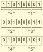
Двоично-десятичный код — форма записи целых чисел, когда каждый десятичный разряд числа записывается в виде его четырёхбитного двоичного кода. Например, число 31110 будет записано в двоичной системе счисления в двоичном коде как 1 0011 01112, а в десятичной системе счисления в двоично-десятичном коде как 0011 0001 000110.
Преимущества и недостатки
Преимущества
- Упрощён вывод чисел на индикацию — вместо последовательного деления на 10 требуется просто вывести на индикацию каждый полубайт. Аналогично, проще ввод данных с цифровой клавиатуры.
- Для дробных чисел (как с фиксированной, так и с плавающей запятой) при переводе в человекочитаемый десятичный формат и наоборот не теряется точность.
- Упрощены умножение и деление на 10, а также округление.
По этим причинам двоично-десятичный формат применяется в калькуляторах — калькулятор в простейших арифметических операциях должен выводить в точности такой же результат, какой подсчитает человек на бумаге.
Недостатки
- Усложнены арифметические операции.
- Требует больше памяти.
- В двоично-десятичном коде 8421-BCD существуют запрещённые комбинации битов:
| Запрещённые в 8421-BCD битовые комбинации | ||
|---|---|---|
| 1010 | 1011 | 1100 |
| 1101 | 1110 | 1111 |
Запрещённые комбинации возникают обычно в результате операций сложения, так как в 8421-BCD используются только 10 возможных комбинаций 4-х битового поля вместо 16.
Поэтому, при сложении и вычитании чисел формата 8421-BCD действуют следующие правила:
- При сложении двоично-десятичных чисел каждый раз, когда происходит перенос бита в старший полубайт, необходимо к полубайту, от которого произошёл перенос, добавить корректирующее значение 0110.
- При сложении двоично-десятичных чисел каждый раз, когда встречается недопустимая для полубайта комбинация, необходимо к каждой недопустимой комбинации добавить корректирующее значение 0110 с разрешением переноса в старшие полубайты.
- При вычитании двоично-десятичных чисел, для каждого полубайта, получившего заём из старшего полубайта, необходимо провести коррекцию, отняв значение 0110.
Пример операции сложения двоично-десятичных чисел:
Требуется: Найти число A = D + C, где D = 3927, C = 4856
Решение:
Представим числа D и C в двоично десятичной форме:
D = 3927 = 0011 1001 0010 0111
C = 4856 = 0100 1000 0101 0110
Суммируем числа D и С по правилам двоичной арифметики:
       *         **
  0011 1001 0010 0111
+ 0100 1000 0101 0110
  ___________________
= 1000 0001 0111 1101 - Двоичная сумма
+      0110      0110 - Коррекция
  ___________________
  1000 0111 1000 0011
‘*’ — тетрада, из которой был перенос в старшую тетраду
‘**’ — тетрада с запрещённой комбинацией битов
В тетраду помеченую символом * добавляем шестёрку т.к по правилам двоичной арифметики перенос унёс с coбой 16, а по правилам десятичной арифметики должен был унести 10.
В тетраду помеченую символом ** добавляем шестёрку и разрешаем распространение переноса так как комбинация битов 1101 (что соответствует десятичному числу 13) является запрещённой.
См. также
- Позиционные системы счисления
- Десятичная система счисления
- Двоичная система счисления
Ссылки
Эта страница использует содержимое раздела Википедии на русском языке. Оригинальная статья находится по адресу: Двоично-десятичный код. Список первоначальных авторов статьи можно посмотреть в истории правок. Эта статья так же, как и статья, размещённая в Википедии, доступна на условиях CC-BY-SA .
Все
операции в ЭВМ выполняются в двоичной
системе счисления. Однако, человеку
удобно вводить информацию и получать
результаты вычислений в десятичной
системе счисления. Для этого используются,
так называемые, двоично-десятичные
коды. В них
один
десятичный разряд представляют четырьмя
двоичными разрядами (тетрадой). При
помощи четырех бит можно закодировать
шестнадцать различных символов (цифр).
Существует много разных систем кодирования
[10], но наиболее широко применяется код
прямого замещения — код 8–4–2–1 (это веса
двоичных разрядов влево от запятой).
Составим таблицу соответствия
двоично-десятичного кода и десятичных
цифр:
-
Двоично-десятичный
кодДесятичная
цифра8 4
2 10
0
0
0
0
0
0
0
1
1
0
0
1
0
2
0
0
1
1
3
0
1
0
0
4
0
1
0
1
5
0
1
1
0
6
0
1
1
1
7
1
0
0
0
8
1
0
0
1
9
Остальные
комбинации двоичного кода являются
лишними (запрещенными). Запишем пример
двоично-десятичного кода:
1258 = 0001 0010 0101 1000
589 = 0000
0101 1000 1001
Сложение двоично-десятичных чисел
Сложение
двоично-десятичных чисел производится
по правилам двоичной арифметики, с
учетом переносов. Пусть имеем два
десятичных числа А и В. Требуется найти
сумму С = А + В.
В
каждой тетраде выполняется сложение
трёх чисел — двух слагаемых и переноса
из предыдущего разряда, т.е. аn
+ bn
+ pn-1.
При этом
возможны такие ситуации.
1)
аn
+ bn
+ pn-1
< 10 .
А = 14 В = 23 С = А + В = 37
А
= 0001 0100
В
= 0010 0011
С
= 0011 0111
![]() 37 Ответ получился верный.
37 Ответ получился верный.
2)
аn
+ bn
+ pn-1
> 15 .
А = 47 В = 39 С = А + В = 86
А = 0100 0111
В = 0011 1001
С
= 1000
![]() 0000
0000![]() 80 Ответ получился неверный, так
80 Ответ получился неверный, так
как был перенос из младшей тетрады в
старшую. Тетрада переполняется числом
16, т.е. единица межтетрадного переноса
уносит в старшую тетраду 16 , а не 10 единиц
как в десятичной системе счисления (
шесть лишних единиц! ). Поэтому результат
необходимо скорректировать путём
добавки + 6. Выполним коррекцию
С = 1000 0000
0000
0110 — коррекция ( + 6 )
ответ
1000 0110
![]() 86 Ответ правильный.
86 Ответ правильный.
3)
10
![]() аn
аn
+ bn
+ pn-1
![]() 15 А = 47 В = 36 С = А + В =83
15 А = 47 В = 36 С = А + В =83
А = 0100
0111
В = 0011
0110
С
= 0111 1101
![]() Ответ неверный, хотя и нет
Ответ неверный, хотя и нет
межтетрадного переноса, но имеется
запрещённая комбинация. Необходимо
вызвать искусственное переполнение
тетрады путём добавки +6. Выполним
коррекцию
С
= 0111 1101
0000
0110 — коррекция ( + 6 )
ответ
1000![]() 0011
0011![]() 83 Теперь ответ правильный. Внимание!
83 Теперь ответ правильный. Внимание!
Коррекция результата выполняется только
один раз, поэтому межтетрадный перенос
при коррекции не требует ещё одной
коррекции.
Таким
образом, при сложении двоично – десятичных
чисел выполняется коррекция результата
по правилу – если был межтетрадный
перенос (переполнение тетрады) или
получилась запрещённая комбинация, то
к этой тетраде добавляется + 6 (0110).
Ещё
один пример. А = 479 В = 128 С = А
+ В = 607
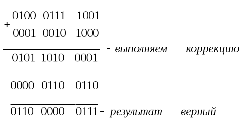
В
старшей тетраде коррекция 0, в средней
— +6 (запрещённая комбинация), в младшей
тетраде +6 ( был перенос ).
Соседние файлы в предмете [НЕСОРТИРОВАННОЕ]
- #
- #
- #
- #
- #
- #
- #
- #
- #
- #
- #
ДВОИЧНО-ДЕСЯТИЧНАЯ СИСТЕМА
Автор-составитель: Ерещенко Александр
Двоично-десятичная система счисления. Десятичные цифры от 0 до 9 заменяются представляющими их двоичными тетрадами: 0=0000, 1=0001, 2=0010, 3=0011, 4=0100, 5=0101, 6=0110, 7=0111, 8=1000 и 9=1001. Такая запись очень часто используется как промежуточный этап перевода числа из десятичной системы в двоичную или обратно. Так как 10 не является точной степенью 2, то используются не все 16 тетрад, а алгоритмы арифметических операций над многозначными числами здесь более сложны, чем в основных системах счисления. И тем не менее, двоично-десятичная система счисления применяется даже на этом уровне во многих микрокалькуляторах и некоторых компьютерах (в частности, «Ямаха» стандарта MSX).
Поскольку человеку наиболее привычны представление и арифметика в десятичной системе счисления, а для компьютера — двоичное представление и двоичная арифметика, была введена компромиссная система двоично-десятичной записи чисел. Такая система чаще всего применяется там, где существует необходимость частого использования процедуры десятичного ввода-вывода. (электронные часы, калькуляторы, АОНы, и т.д.). В таких устройсвах не всегда целесообразно предусматривать универсальный микрокод перевода двоичных чисел в десятичные и обратно по причине небольшого объема программной памяти.
Принцип построения этой системы достаточно прост: каждая десятичная цифра преобразуется прямо в свой десятичный эквивалент из 4 бит, например:
369110=0011 0110 1001 0001DEC:
Десятичное число 3 6 9 1
Двоично-десятичное число 0011 0110 1001 0001
Преобразуем двоично-десятичное число 1000 0000 0111 0010 в его десятичный эквивалент.
Каждая группа из 4 бит преобразуется в её десятичный эквивалент.
Получим 1000 0000 0111 0010DEC = 807210:
Двоично-десятичное число 1000 0000 0111 0010
Десятичное число 8 0 7 2
Микропроцессоры используют чистые двоичные числа, однако понимают и команды преобразования в двоично-десятичную запись. Полученные двоично-десятичные числа легко представимы в десятичной записи, более понятной людям.
Преобразование двоичных чисел в двоично-десятичные
Арифметико-логическое устройство AVR-микроконтроллеров (как и других микропроцессоров) выполняет элементарные арифметические и логические операции над числами, представленными в двоичном коде. В двоичном коде считываются результаты преобразования АЦП, в двоичном коде (в формате целых чисел или чисел с плавающей точкой) удобно выполнять обработку результатов измерения. Однако, когда окончательный результат отображается на индикаторе, он должен быть преобразован в десятичный формат, удобный для восприятия человеком.
В данном разделе рассматриваются программы преобразования двоичных чисел в двоично-десятичные.
1. Форматы представления десятичных чисел
В настоящее время распространены два формата представления десятичных чисел в микропроцессорах — упакованный двоично-десятичный код (BCD-Binary-Coded Decimal) и неупакованный десятичный код [1].
Упакованный BCD-код — это такое представление десятичного числа, когда каждая десятичная цифра представляется 4-х битным двоичным позиционным кодом 8-4-2-1. При этом байт содержит две десятичные цифры. Младшая десятичная цифра занимает правую тетраду (биты 3 : 0), старшая — левую тетраду (биты 7 : 4). Многоразрядные BCD-числа занимают несколько смежных байт. Если число является знаковым, то для представления знака в BCD-формате отводится старшая тетрада старшего байта. Для кодирования знака можно использовать шесть двоичных кодовых комбинаций, которые не используются для представления десятичных цифр. Это коды 1010-1111 (A-F в шестнадцатеричном представлении). Обычно для кодирования знака плюс применяют код 1100 (С), а для знака минус — 1101 (D).
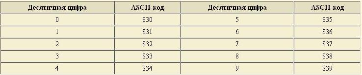
Неупакованный десятичный код является подмножеством международной таблицы кодирования символов ASCII (Таблица 1). Видно, что для хранения неупакованных десятичных чисел требуется в два раза больше памяти, так как каждая цифра представляется 8-битным кодом.
Таблица 1: ASCII-коды десятичных цифр
2. Преобразование целых 16-битных чисел в двоично-десятичные числа
На сайте www.atmel.com предлагается программа «bin2bcd16» для преобразования целых 16-битных двоичных чисел в двоично-десятичные упакованные числа. В данной статье рассматривается программа «bin16bcd5» (см. Приложение, Программа 1), написанная Терешкиным А. В. согласно алгоритму, изложенному в [1], и выполняющая ту же задачу.
Последняя программа по быстродействию, длине кода и количеству используемых регистров оказалась более эффективной, чем первая.
Алгоритм программы «bin16bcd5» заключается в следующем. Предположим, что имеется целое беззнаковое 16-битное число (диапазон от 0 до 65535). Очевидно, что необходимо найти 5 десятичных цифр. Способ преобразования заключается в том, чтобы, вычитая из исходного числа число 10000, сначала определить десятичную цифру десятков тысяч. Затем находится цифра тысяч последовательным вычитанием числа 1000 и т. д. Вычитание каждый раз производится до получения отрицательной разности с подсчетом числа вычитаний. При переходе к определению каждого следующего десятичного разряда в регистрах исходного числа восстанавливается последняя положительная разность. После того, как будет найдена десятичная цифра десятков, в регистрах исходного числа останется десятичная цифра единиц.
Программа «bin16ASCII5» (см. Приложение, Программа 2) преобразует целое двоичное 16-битное число в десятичное неупакованное число. При этом используется тот же алгоритм.
3. Преобразование двоичной дроби в двоично-десятичную дробь
Двоичная дробь, по определению, представляется следующим выражением:
0.A-1A-2 … A-m = A-1*2-1 + A-2*2-2 + … A-m*2-m
Из этого представления следует алгоритм преобразования (Рис. 2), который содержит m шагов. На каждом шаге к двоично-десятичному результату прибавляется очередная двоичная цифра и весь результат делится на 2.
На изображены двоичный регистр, который содержит исходную двоичную дробь и регистр двоично-десятичного упакованного результата. Для наглядности у обоих регистров также показаны разряд единиц и положение точки, которые в памяти микропроцессора никак не представлены, но положение которых всегда строго оговорено. Количество циклов рассматриваемого алгоритма равно количеству бит двоичной дроби. Разрядность двоично-десятичного регистра определяется требуемой точностью вычислений.
Сложить эту цифру с двоично-десятичным числом означает, что ее нужно поместить в разряд единиц двоично-десятичного числа, откуда при последующем делении на два цифра A-i сдвинется в старший разряд старшей тетрады десятичной дроби. При программировании мы можем представлять, что разрядом единиц десятичной дроби является бит переноса С.
При делении на два двоично-десятичного упакованного числа, так же как и при делении двоичного числа, его сдвигают вправо на один разряд. При этом на два делится каждая тетрада, то есть каждая десятичная цифра. При делении четной десятичной цифры в соответствующем разряде снова получается десятичная цифра, и никакой коррекции не требуется. При делении на 2 нечетной десятичной цифры остаток, равный 5, должен быть добавлен к более младшему десятичному разряду, но на самом деле при двоичном сдвиге в более младшую тетраду добавляется число 8 (вес старшего разряда тетрады). Поэтому требуется коррекция результата, которая заключается в вычитании числа 3 из содержимого тех тетрад, которые после сдвига вправо имеют установленные старшие разряды.
4. Преобразование чисел с плавающей точкой в двоично-десятичные числа
Представление чисел с плавающей точкой имеет следующий вид:
± M * 2 ± П
где М — двоичная мантисса числа, П — двоичный порядок числа.
Такое представление часто используется и в десятичной системе счисления для представления очень больших или очень малых чисел. Мантисса и порядок представляют собой целые знаковые числа. Знак мантиссы является знаком всего числа. Порядок показывает истинное положение точки вместо того, которое она занимает в изображении мантиссы. Двоичное число с плавающей точкой отличается от привычного нам десятичного тем, что точка является двоичной, то есть порядок показывает на количество двоичных (а не десятичных) разрядов, на которое необходимо переместить эту точку влево или вправо.
Нормализованным представлением числа с плавающей точкой называют такое представление, когда мантисса является правильной дробью, и старшая ее цифра отличается от нуля. Но для двоичного числа требование того, что старшая цифра отличается от нуля означает, что эта цифра равна 1. Если старшая цифра точно известна, то ее можно не хранить в памяти.
Тест
1. ДВОИЧНО-ДЕСЯТИЧНАЯ СИСТЕМА СЧИСЛЕНИЯ
2. Преобразование двоичных чисел в двоично-десятичные

Люба Снежкова
Эксперт по предмету «Информатика»
Задать вопрос автору статьи
Понятие смешанной системы счисления
Среди систем счисления выделяют класс так называемых смешанных систем счисления.
Определение 1
Смешанной называется такая система счисления, в которой числа, заданные в некоторой системе счисления с основанием $P$ изображаются с помощью цифр другой системы счисления с основанием $Q$, где $Q
При этом в такой системе счисления во избежание разночтения для изображения каждой цифры системы с основанием $P$ отводится одинаковое количество разрядов системы с основанием $Q$, достаточное для представления любой цифры системы с основанием $P$.
Примером смешанной системы счисления является двоично-десятичная система.
Практическое обоснование использования двоично-десятичной системы счисления
Поскольку человек в своей практике широко использует десятичную систему счисления, а для компьютера свойственно оперирование двоичными числами и двоичной арифметикой, был введен в практику компромиссный вариант — система двоично-десятичной записи чисел, которая, как правило, используется там, где присутствует необходимость частого использования процедуры десятичного ввода-вывода (например, электронные часы, калькуляторы и т.д.). В подобных устройствах не всегда целесообразно применять универсальный микрокод перевода двоичных чисел в десятичные и обратно по причине малого объема программной памяти.
Замечание 1
В некоторых типах ЭВМ в арифметико-логических устройствах (АЛУ) имеются специальные блоки десятичной арифметики, которые выполняют операции над числами, представленными в двоично-десятичном коде. Это позволяет в некоторых случаях существенно повысить производительность ЭВМ.
К примеру, в автоматизированной системе обработки данных используется большое количество чисел, а вычислений при этом немного. В подобном случае операции перевода чисел из одной системы в другую существенно превысили бы время выполнения операций по обработке информации.
Микропроцессоры же используют чистые двоичные числа, однако при этом понимают и команды преобразования в двоично-десятичную запись.
АЛУ AVR-микроконтроллера (как и других микропроцессоров) выполняет элементарные арифметические и логические операции над числами, представленными в двоичном коде, а именно:
-
считывает результаты преобразования АЦП;
-
в формате целых чисел или чисел с плавающей точкой выполняет обработку результатов измерения.
«Двоично-десятичная система счисления» 👇
Однако окончательный результат при этом выводится на индикатор в десятичном формате, удобном для восприятия человеком.
Принципы построения двоично-десятичной системы счисления
При построении двоично-десятичной системы счисления для изображения каждой десятичной цифры в ней отводится $4$ двоичных разряда, поскольку максимальная десятичная цифра $9$ кодируется как $10012$.
Например: $925_{10} = 1001 0010 0101_{2-10}$.
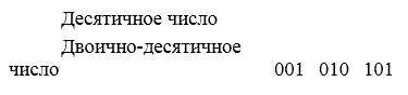
Рисунок 1.
В данной записи последовательные четверки двоичных разрядов изображают цифры $9$, $2$ и $5$ десятичной записи соответственно.
Для записи числа в двоично-десятичной системе счисления его необходимо сначала представить в десятичной системе, а затем каждую, входящую в состав числа, десятичную цифру представить в двоичной системе. При этом для написания различных десятичных цифр в двоичной системе счисления требуется разное количество двоичных разрядов. Чтобы обойтись без применения каких-либо разделительных знаков, при двоичном изображении десятичной цифры всегда записывается 4 двоичных разряда. Группа из этих четырех разрядов называется тетрадой.
Хотя в двоично-десятичной записи используются только цифры $0$ и $1$, она отличается от двоичного изображения данного числа, так как десятичный эквивалент двоичного числа в несколько раз больше десятичного эквивалента двоично-десятичного числа.
Например:
$1001 0010 0101_{(2)} = 2341_{(10)}$,
$1001 0010 0101_{(2)} = 925_{(2-10)}$.
Такая запись довольно часто используется как промежуточный этап при переводе числа из десятичной системы в двоичную и обратно. Так как число $10$ не является точной степенью числа $2$, то используются не все $16$ тетрад (тетрады, изображающие числа от $A$ до $F$ отбрасываются, так как эти числа считаются запрещенными), алгоритмы же арифметических операций над многозначными числами в этом случае более сложные, чем в основных системах счисления. И, тем не менее, двоично-десятичная система счисления используется даже на этом уровне во многих микрокалькуляторах и некоторых компьютерах.
Чтобы откорректировать результаты арифметических операций над числами, представленными в двоично-десятичном коде, в микропроцессорной технике используются команды, которые преобразуют результаты операций в двоично-десятичную систему счисления. При этом используется следующее правило: при получении в результате операции (сложения или вычитания) в тетраде числа, большего, чем $9$, к этой тетраде прибавляют число $6$.
Например: $75+18=93$.
$+00011000$
$10001101 (8D)$
В младшей тетраде появилась запрещенная цифра $D$. Прибавим к младшей тетраде $6$ и получим:
$+00000110$
$10010011 (93)$
Как видим, несмотря на то, что сложение осуществлялось в двоичной системе счисления результат операции получился в двоично-десятичной.
Замечание 2
Поразрядное уравновешивание часто осуществляют на основе двоично-десятичной системы счисления. Применение двоичной и двоично-десятичной системы счисления наиболее целесообразно, поскольку в этом случае число тактов уравновешивания оказывается наименьшим среди прочих систем счисления. Заметим, что применение двоичного кода позволяет примерно на $20%$ уменьшить время обработки компенсирующего напряжения по сравнению с двоично-десятичным.
Преимущества использования двоично-десятичной системы счисления
Преобразование чисел из десятичной системы в двоично-десятичную систему счисления не связано с вычислениями и его легко реализовать, используя при этом простейшие электронные схемы, так как преобразовывается небольшое количество (4) двоичных цифр. Обратное же преобразование происходит в ЭВМ автоматически с помощью особой программы перевода.
Применение двоично-десятичной системы счисления совместно с одной из основных систем счисления (двоичной) позволяет разрабатывать и создавать высокопроизводительные ЭВМ, так как использование блока десятичной арифметики в АЛУ исключает при решении задач необходимость программированного перевода чисел из одной системы счисления в другую.
Поскольку две двоично-десятичные цифры составляют $1$ байт, с помощью которого можно представить значения чисел от $0$ до $99$, а не от $0$ до $255$, как при использовании $8$-разрядного двоичного числа, то используя $1$ байт для преставления каждых двух десятичных цифр, можно формировать двоично-десятичные числа с любым требуемым числом десятичных разрядов.
Находи статьи и создавай свой список литературы по ГОСТу
Поиск по теме